
amplifier circuit
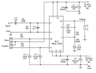
The TDA7294 audio amplifier circuit is designed to provide high-quality sound reproduction in a variety of audio applications. The circuit configuration typically includes the TDA7294 IC, which serves as the primary amplification component. To optimize performance, the circuit should incorporate the necessary passive components such as resistors, capacitors, and inductors that support the desired frequency response and stability of the amplifier.
The power supply for this amplifier should be dual, providing both positive and negative voltages to the TDA7294. This is crucial for the class AB operation, allowing the amplifier to handle both the positive and negative halves of the audio signal effectively. The recommended voltage range for the power supply is typically between ±12V and ±25V, depending on the desired output power and load impedance.
To enhance the performance further, the circuit may include additional features such as a volume control potentiometer, input coupling capacitors to block DC offsets, and output coupling capacitors to prevent DC from reaching the speakers. Implementing proper heat sinking is also essential to dissipate heat generated during operation, ensuring the longevity and reliability of the amplifier.
The inclusion of short circuit and thermal protection circuits is vital for safeguarding the TDA7294 against potential damage due to overload conditions. The thermal protection feature automatically reduces the amplifier output when the chip exceeds its safe operating temperature, while the short circuit protection disables the output when a short circuit is detected.
In summary, the TDA7294 audio amplifier circuit is a versatile and robust solution for high-fidelity audio amplification, capable of delivering excellent sound quality with minimal distortion. Its design allows for easy integration into existing audio systems, making it an attractive option for both DIY enthusiasts and professional audio applications.This is a great audio amplifier circuit based on single power IC TDA7294. TDA7294 is intended for use as a high quality audio class AB amplifier in hi-fi applications. It has very low noise and distortion, wide bandwidth and good output current capability, enabling it to supply high power into both 4 © and 8 © loads. It has both short circuit and thermal protection, so is quite robust. With the addition of a handful of parts and a suitable power supply, this module will deliver over 50W RMS into 4 or 8 ohms with < 0.
1% Total Harmonic Distortion (THD) and < 0. 1% Intermodulation Distortion (IMD). A similar circuit was published in Elektor magazine, 11/96. It is also suitable as a replacement power amp stage, or upgrade for many existing amplifiers of between 30W-50W, provided they have a suitable dual supply, and most do. 🔗 External reference
Related Circuits
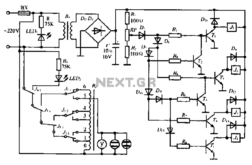
A step-down transformer converts AC 220V to a lower voltage. A diode bridge rectifier and filter capacitor provide a direct current (DC) output, which fluctuates with variations in the grid voltage. A resistive voltage divider is used for sampling....
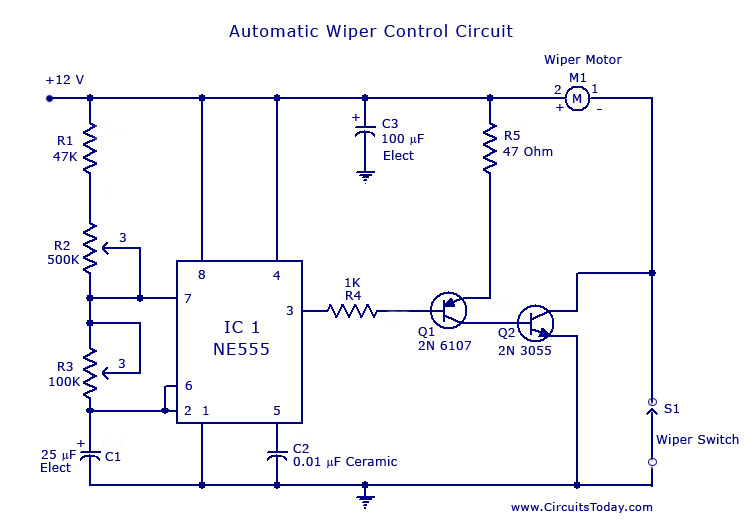
A circuit for car windshield/wiper motor speed control built using an NE 555 IC. This enables intermittent windshield wiper control, which changes the sweep rate to 10 seconds. The circuit utilizes the NE 555 timer IC configured in astable mode...
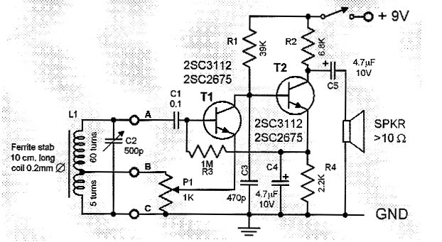
This is a compact and straightforward FM radio receiver capable of tuning into local FM stations. Its minimalistic design renders it suitable for various applications. The FM radio receiver circuit typically consists of several key components that work together to...
This simple charger utilizes a single transistor as a constant current source. The voltage across the pair of 1N4148 diodes biases the base of the BD140 medium power transistor. The circuit operates by employing the BD140 transistor to regulate the charging...
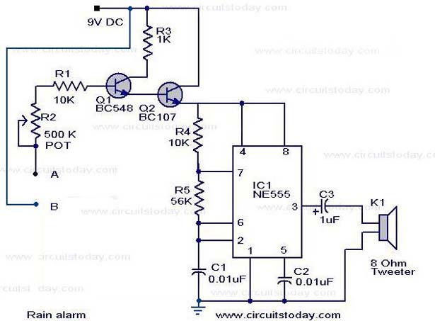
The operation of the rain alarm circuit is explained in detail. The rain alarm project is outlined along with a circuit diagram. The rain alarm circuit is designed to detect the presence of rain and alert users through an audible...
A zero-crossing detector converts an input sine wave (Vin) into a square wave, which, when high, charges an op-amp integrator. A reference-input square wave subsequently discharges the integrator. The output voltage of the integrator at the end of this...
Warning: include(partials/cookie-banner.php): Failed to open stream: Permission denied in /var/www/html/nextgr/view-circuit.php on line 713
Warning: include(): Failed opening 'partials/cookie-banner.php' for inclusion (include_path='.:/usr/share/php') in /var/www/html/nextgr/view-circuit.php on line 713