
Common low-pass filter circuit b
The low-pass filter circuit serves as an essential component in various electronic applications where it is necessary to eliminate high-frequency noise while allowing low-frequency signals to pass through. The circuit typically consists of passive components such as resistors, capacitors, and inductors, which are arranged in a configuration that defines the cutoff frequency.
In the configurations shown in Figures (a) to (c), the filter effectively attenuates frequencies above a certain threshold, thereby protecting sensitive components from high-frequency interference. This feature is particularly beneficial in audio processing, radio frequency applications, and digital signal processing, where signal integrity is paramount.
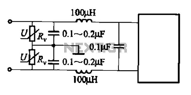
Figure (b) introduces a varistor, which is a voltage-dependent resistor that provides transient voltage suppression. This is particularly useful in applications exposed to lightning strikes or other high-voltage transients, as the varistor can shunt excessive voltage away from sensitive components, thus preventing damage.
Figure (d) highlights the circuit's capability to suppress low-frequency interference, which may arise from power supply fluctuations or other sources of noise. This suppression is crucial in maintaining the stability and reliability of electronic systems.
Figure (f) illustrates the application of the low-pass filter for power supply decoupling. In this context, the filter helps to smooth out voltage fluctuations and reduce ripple in the power supply line, ensuring that downstream components receive a clean and stable voltage.
The choice of components and configuration in a low-pass filter circuit should be tailored to the specific requirements of the application, including the desired cutoff frequency, the level of attenuation needed, and the nature of the interference to be suppressed. Common low-pass filter circuit commonly used low-pass filter circuit is shown. Figure (a) ~ (c) suppress high-frequency interference; Figure (b) of the varistor foot can absorb lightning surge voltage; Fig. (D) suppress low interference; FIG. (F) for the power supply decoupling. You can choose to use depending on the circumstances.
Related Circuits
The circuit integrates several functions, including a smooth startup for the AC power line, with a one-second delay before connecting to the power supply transformers of the amplifier through relay RL1 and resistor Rx. This delay is designed to...
White LEDs have a rated current at a voltage drop of about 3.3 to 3.4 V. It is ideal to be powered from the battery voltage which is slightly larger. Then there is the best energy used. In this...
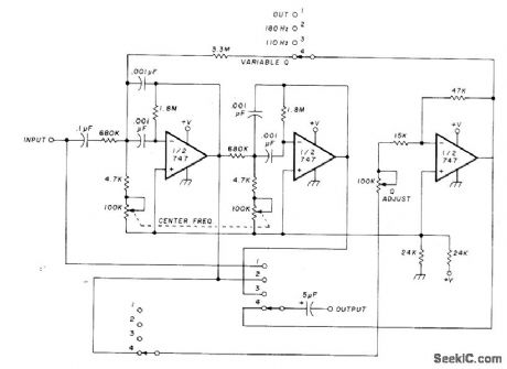
The circuit utilizing Optical Electronics 9803 operational amplifiers separates an audio frequency (AF) input signal into two outputs. The low-pass output allows frequencies from DC up to 10 Hz, while the high-pass output encompasses frequency content above 10 Hz,...
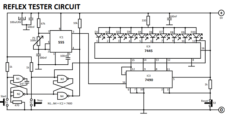
The concept for this crystal tester circuit originated from the necessity to evaluate a large quantity of oscillator crystals that were not in use within a hobby box. Testing each crystal individually without the proper equipment would have been...
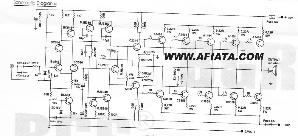
How many speakers can be attached to this amplifier, and what are the impedance and wattage values of these speakers? Please respond to my email. Sir, you made this amplifier, and it works properly for a lifetime. Which transformer...
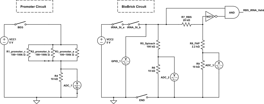
The kit employs an off-the-shelf microcontroller based on the AtMega328P-PU Arduino, along with a simplified version designed for ease of replication and modification by collaborators and students. This initiative aims to enable the fabrication of simplified microcontrollers for DIY...