
Crystal Tester Circuit
The circuit operates on a straightforward principle of oscillation. The heart of this tester is the crystal oscillator formed by the combination of the crystal and transistor T1. When a functional crystal is connected, it resonates at its specified frequency, leading to oscillation. Capacitors C1 and C2 are critical for ensuring that the oscillation is stable and can be effectively measured. They create a voltage divider that allows a portion of the oscillating signal to be fed back to the transistor, maintaining the oscillation.
The output of the oscillator is a sine wave, which is then processed by the rectifier circuit composed of diodes D1 and D2. This rectification converts the AC signal into a pulsating DC signal, which is further smoothed by capacitor C4. This filtering is essential for providing a stable DC voltage to the base of transistor T2. The base-emitter junction of T2 acts as a switch; when the voltage exceeds a certain threshold, T2 turns on, allowing current to flow through the LED, thus illuminating it.
In summary, this crystal tester circuit offers an efficient and cost-effective solution for hobbyists and engineers alike to test oscillator crystals quickly and accurately. Its design leverages basic electronic components to achieve functionality that rivals more expensive commercial alternatives. The simplicity of the circuit allows for easy assembly and troubleshooting, making it an ideal project for those looking to enhance their understanding of oscillator circuits and crystal technology.The idea for this crystal tester circuit sprung out of the need of testing a large number of oscillator crystals lying unused in a big hobby box. testing the crystals one by one without the appropriate device would have been very slow and a time consuming task.
Commercial crystal testers are however very expensive, that is why this simple electron ic crystal tester was born. The transistor T1 and the crystal to be tested together makes a complete crystal oscillator. The capacitors C1 and C2 works as a capacitive voltage divider that is connected to the transistor T1. If the crystal being tested is intact, the circuit oscillates. The sine wave oscillation voltage is fed to the rectifier circuit (d1, D2) and filtered by capacitor C4.
With an intact crystal, the DC voltage at the base of the transistor T2 is high enough to cause the transistor to conduct. The LED lights up signalling that the crystal is good. 🔗 External reference
Related Circuits
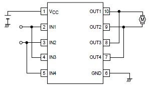
A simple forward-reverse motor control driver electronic circuit can be designed using the LB1948M, a two-channel low saturation voltage forward-reverse motor control driver IC. The LB1948M motor driver is suitable for use in 12V system products and can drive...
This audio mixer circuit schematic is designed around four current-controlled amplifiers, all integrated within the SSM2024 IC. The audio mixer circuit utilizes the SSM2024 integrated circuit, which features low-noise, high-performance operational amplifiers suitable for audio applications. The SSM2024 is particularly...
A 6V to 12V DC converter circuit is designed to convert a lower voltage of approximately 6 volts to a higher voltage of 12 volts, albeit with a reduced current rating. This inverter circuit can deliver up to 800mA...
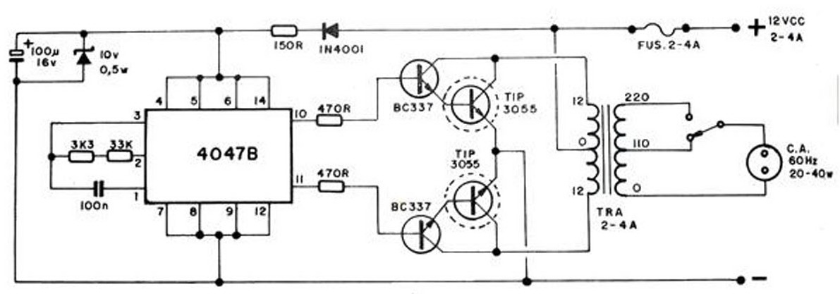
The converter transforms 12 VDC to 220 VAC, allowing for the conversion of 12 volts DC into 220 volts AC. The circuit diagram provided illustrates a simple converter circuit. This DC to AC converter can supply voltage for a...
This receiver, designed around the popular ZN414 integrated circuit, operates within the AM band frequency range of 550 to 1600 KHz. For Longwave reception, it is necessary to replace the coil, which can be sourced from an old medium...
The loop can be any type of hookup wire, with a maximum resistance of about 90K. Using very thin wire (40AWG, for example) will create a highly sensitive trip wire, but will reduce the distance it can be strung...