
Filter Circuit
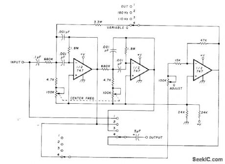
The circuit functions as an automatic DC level shifter, negating the need for an additional buffer amplifier due to the op-amp's near-zero output impedance. The design theory is elaborated in various articles, including the design of high-Q active bandpass filters that automatically track input signal frequencies over a range of 10:1, even in the presence of noise. When the signal moves outside the tracking range, the circuit sweeps between low and high-frequency limits until a suitable signal is detected. This configuration employs the Optical Electronics 3704 active filter in conjunction with 5898 analog multipliers. The 9813 operational amplifier, configured as a Schmitt trigger, serves as the primary component of the scanning circuit, which operates within a frequency range of 160 to 1600 Hz, providing an FM bandwidth of 20 Hz for the error voltage output.
For applications requiring less than 100% bandwidth, a single 741 or equivalent operational amplifier can be utilized, with a fixed gain of -2Q², where Q is the reciprocal of the damping factor d, varying from less than 1 to above 100. The Q factor can be adjusted by altering the ratio of input and feedback resistors while maintaining a constant product. For a Q value of 3, the feedback resistor should be 36 times the value of the input resistor.
The universal filter design features simultaneous low-pass, bandpass, high-pass, and notch outputs, all with a cutoff frequency of 1 Hz. To scale the circuit to a 1 kHz cutoff, the 10-megohm resistors should be replaced with 10 kΩ components. This configuration offers a bandwidth of 2000 Hz and a midband gain of 1 for applications requiring a narrow-bandwidth bandpass active filter, with a detailed design procedure provided.
The Exar XR-215 phase-locked loop integrated circuit (PLL IC) is capable of tracking input signals over a 3:1 frequency range, centered around the free-running frequency of the voltage-controlled oscillator (VCO). The maximum tracking range occurs when pin 10 is left open, with R0 typically ranging between 1 kΩ and 4 kΩ, while C1 should be 30 to 300 times the value of C0, where C0 is the timing capacitor dependent on the center frequency. This system can also function as a linear discriminator or an analog frequency meter across the same 3:1 input frequency change, with RF set to 36 kΩ.
The center frequency of the filter is automatically adjusted to track the input signal frequency, optimizing noise rejection for varying input frequencies, which is common in many vibrating transducers. This design does not require a reference frequency or internal oscillator, allowing for decade-step frequency range extension through capacitor switching. When the filter is not tuned to the input frequency, the phase shift is not 180 degrees, prompting the phase detector to apply an error signal to the gate of a field-effect transistor (FET), controlling its drain-source resistance. The phase detector, along with components A4, A5, CR2, and CR3, forms part of a negative feedback loop around the filter, retuning it based on phase error. The article also provides design equations, operational details, and waveforms observed at various circuit points.Circuit using optical Electronics 9803 opamps separates AF input signal into two outputs. Low-pass output contains DC to 10 Hz, and high-pass output has frequency content above 10 Hz to upper frequency limit approaching 10 MHz for opamp used. Dynamic output impedance of both outputs is less than 1 ohm. Both outputs have DC continuity. DC output of high-pass terminal is equal to offset voltage of integrator. DC output of low-pass terminal equals DC input plus offset voltages of both opamps. - Automatic DC Level Shifter, Optical Electronics, Tucson, AZ, Application Tip 10226. (View) Uses opamp in circuit having essentially zero output impedance, making additional buffer amplifier unnecessary. Article gives design theory and covers many other types of notch filters. -Y. Nezer, Active Notch Filters, Wireless World, July 1975, p 307-311. (View) High-Q active bandpass filter automatically tracks input signal frequency over 10:1 range in presence of noise.
When signal goes outside tracking range, circuit sweeps between low- and high-frequency limits until suitable signal reappears. Circuit is basically voltage-controlled bandpass filter using Optical Electronics 3704 active filter with 5898 analog multipliers.
9813 opamp connected as Schmitt trigger is main element of scanning circuit. Frequency range is 160 to 1600 Hz, and FM bandwidth of error-voltage output is 20 Hz. - Frequency Tracking Active Filter, Optical Electronics, Tucson, AZ, Application Tip 10270. (View) Single 741 or equivalent opamp is suitable for applications where bandwidth is less than 100%. Gain is fixed at -2Q2, where Q is reciprocal of damping d and ranges from less than 1 to above 100. Q is changed by varying ratio of input and feedback resistors while keeping their product constant. For Q of 3, feedback resistor should be 36 times value of input resistor. -D. Lancaster, Active-Filter Cookbook, Howard W. Sams, Indianapolis, IN, 1975, p 150-154. (View) Universal filter has simultaneous low-pass, bandpass, high-pass, and notch outputs all with cutoff frequency of 1 Hz.
To scale circuit up to 1-kHz cutoff, replace 10-megohm resistors with 10K. -D. Lancaster, CMOS Cookbook, Howard W. Sams, Indianapolis, IN, 1977, p 343-344. (View) Provides bandwidth of 2000 Hz and midband gain of 1 for applications requiring narrow-bandwidth bandpass active filter. Design procedure is given. - Audio Handbook, National Semiconductor, Santa Clara, CA, 1977, p 2-52-2-53. (View) Connection shown for Exar XR-215 PLL IC tracks input signal over 3:1 frequency range centered on free, running frequency of VCO.
Tracking range is maximum when pin 10 is open. R0 is typically between 1K and 4K. C1 is between 30 and 300 times C0 where timing capacitor C0 depends on center frequency. System can also be operated as linear discriminator or analog frequency meter covering same 3:1 change of input frequency. RF can be 36K. - Phase-Locked Loop Data Book, Exar Integrated Systems, Sunnyvale, GA, 1978, p 21-28. (View) Center frequency of filter is automatically adjusted to track signal frequency, for optimum noise rejection when input frequency varies over wide range as it does with many types of vibrating transducers.
Requires no reference frequency and no intemal oscillator or synchronizing circuits. Flequency range can be extended in decade steps by capacitor switching. When filter is not tuned to input frequency, phase shift is not 180 ° and phase detector applies error signal to gate of FET to control its drain-source resistance. Phase detector A4-A5-CR2-CR3 and FET form part of negative-feedback loop around filter, so error in phase changes resistance of FET and thereby retunes filter, Article gives design equations, operational details, and waveforms at various points in circuit.
-G. J. Deboo and R. C. Hedlund, Automatically Tuned Filter Uses IC Operational Amplifiers, EDN/EEE Magazine, Feb. 1, 1972, p 38-41. (View) Provides passband 🔗 External reference
Related Circuits
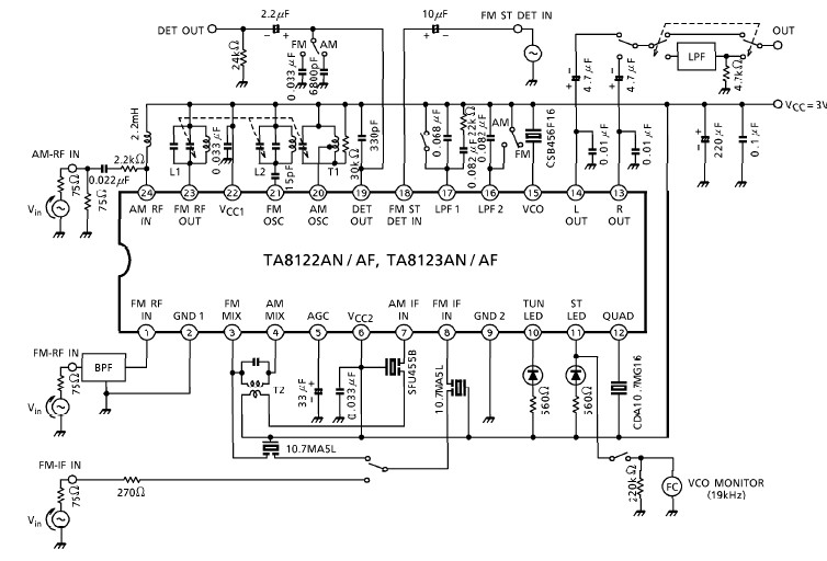
A simple low-power AM/FM radio receiver electronic project can be designed using the TA8122 integrated AM/FM receiver, manufactured by Toshiba Semiconductor. This radio receiver circuit can be utilized for portable radio applications or similar devices. The TA8122 radio receiver...
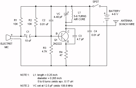
The electret microphone operates with a current of 200 µA, which varies by ±3 µA in response to sound waves. This variation results in a voltage of 2V across resistor R1 and 4V across the microphone. As sound waves...
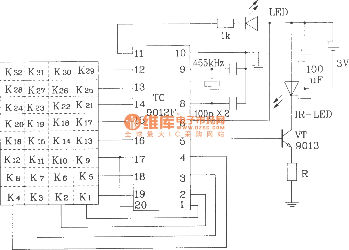
The TC9012 is a specialized off-screen remote control code transmitter. It incorporates an oscillator, divider timing generator, system code latch, data storage, key scan input, key scan output, and carrier control and output units. The internal 8-bit system code...
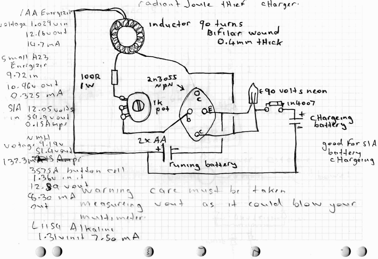
A high power joule thief circuit is explained in this post, which can be constructed by any new hobbyist. Here is the simplified drawing of the radiant joule thief battery charger. The inductor was wound with many turns until...
The external audio spectrum display circuit is designed for high-end audio equipment, providing both real-time playback signal analysis and visually appealing effects. This display does not require any electrical connections to the sound equipment; it can simply be placed...
This page presents a circuit featuring twenty open collector outputs that activate sequentially in a continuous, unidirectional loop. The circuit utilizes the 74LSxx family of TTL integrated logic devices. It is designed to drive light-emitting diodes or low current,...