
Common non-sinusoidal oscillator circuit waveform square wave oscillator self-excited multivibrator
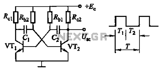
The common non-sinusoidal oscillator circuit, specifically the square wave oscillator, is a fundamental electronic circuit utilized to generate square wave signals. It operates based on the principles of self-excitation, where the circuit relies on feedback to maintain oscillation without the need for an external signal source.
Typically, this type of oscillator employs active components such as transistors or operational amplifiers, along with passive components like resistors and capacitors, to define its frequency of oscillation and waveform characteristics. The square wave output is characterized by its rapid transitions between high and low states, which can be utilized in various applications including clock generation, signal modulation, and timing circuits.
The frequency of oscillation in a self-excited multivibrator can be derived from the timing components in the circuit. For a basic astable multivibrator configuration using two identical resistors (R) and capacitors (C), the frequency (f) of oscillation can be approximated by the formula:
\[ f = \frac{1}{T} = \frac{1}{(0.693)(R_1 + R_2)C} \]
where \( T \) is the period of oscillation. The duty cycle, which defines the ratio of the high state duration to the total period, can also be adjusted by varying the resistor and capacitor values, allowing for flexibility in output waveform characteristics.
In practical implementations, careful selection of component values is crucial to achieve the desired frequency and stability of the oscillator. The performance of the oscillator may also be influenced by external factors such as temperature and supply voltage variations, which should be considered during design.
Overall, the square wave oscillator is a versatile and essential circuit in the field of electronics, serving as a building block for more complex systems and applications. Common non-sinusoidal oscillator circuit, waveform and frequency formula - square wave oscillator - self-excited multivibrator
Related Circuits
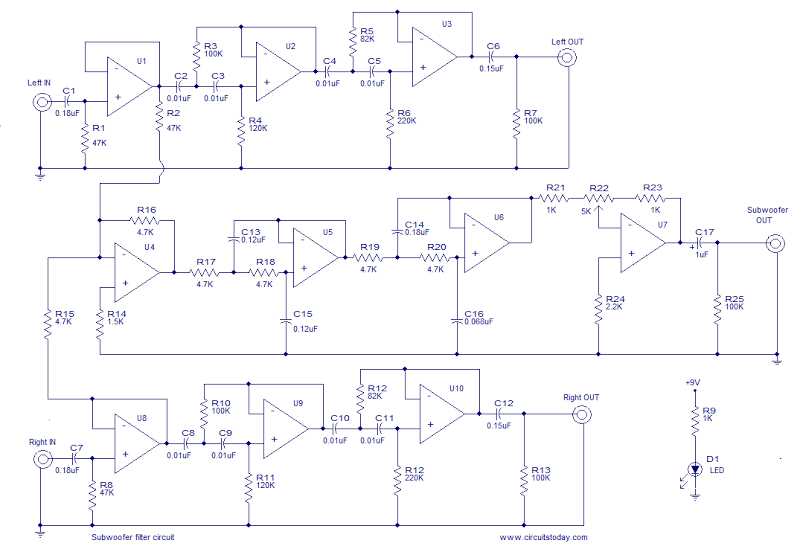
This is the schematic diagram of an operational amplifier (op-amp) based subwoofer filter. Audio frequencies below 200 Hz are typically categorized within the subwoofer range, indicating that a subwoofer filter should have a cutoff frequency around 200 Hz. The...
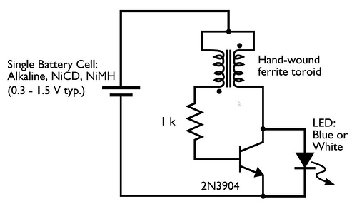
This circuit is commonly referred to as a Joule Thief, and it has been frequently encountered in various electronics videos on YouTube. The Joule Thief is a simple, low-cost circuit designed to extract energy from a single-cell battery, particularly when...
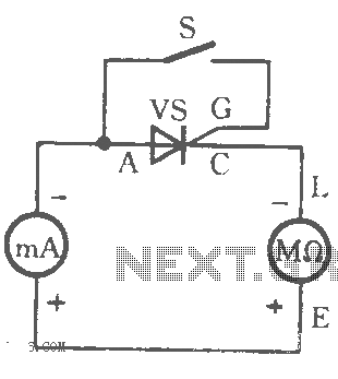
The table illustrates the capability to trigger the thyristor circuit diagram. The thyristor circuit diagram serves as a fundamental component in various electronic applications, particularly in power control and switching. A thyristor is a four-layer semiconductor device that functions as...

This circuit is a 6-zone alarm system designed for independent operation, suitable for small office or home environments. It can be adapted to utilize a combination lock or keypad for setting and resetting the alarm. All zones, Z1 to...
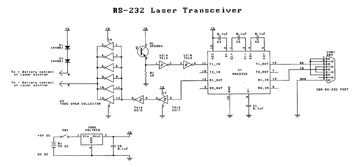
Laser based projects used to be expensive, until the development of solid state lasers. This project is designed for the entry level laser experimenter. The circuit allows any two computers with serial (RS-232) communication capability to communicate over 200...
This circuit is a single transistor flyback (Joule Thief) circuit that features a third coil. With it, flash duration and brightness are significantly enhanced. The single transistor flyback circuit, commonly known as a Joule Thief, is designed to efficiently convert...