
Acceleration Monitor using ADXL202 and AVR
The AccelR8 schematic is designed to provide a compact and efficient solution for measuring acceleration using minimal components. The AVR 8515 microcontroller serves as the central processing unit, executing the necessary algorithms to interpret the data received from the ADXL202 accelerometer. The MAX603 voltage regulator ensures that the microcontroller and the accelerometer operate within their specified voltage ranges, providing stable power during operation.
The ADXL202 accelerometer employs a unique micro-machined structure that is sensitive to acceleration forces. This structure, which is part of a capacitor, experiences deflection when subjected to acceleration, allowing for precise measurement of movement along one axis. The output from the ADXL202 is a variable duty-cycle square wave, where the duty cycle correlates directly with the magnitude of the acceleration detected.
The AVR 8515 microcontroller processes this output by measuring the pulse width and period of the square wave signal. By performing calculations based on these measurements, the microcontroller can accurately determine the acceleration value. This calculated data is then formatted for display, enabling users to visualize the acceleration metrics in real-time.
Overall, the schematic design of the AccelR8 demonstrates an effective integration of these three ICs, resulting in a reliable and efficient system for acceleration measurement and analysis. The combination of the AVR 8515, MAX603, and ADXL202 provides a robust platform for applications requiring precise motion detection and monitoring.The schematic show that the AccelR8 only uses 3 IC`s. An AVR 8515 microcontroller do the calculation work and controls the other circuits. An MAX603 controls voltage and power-on/power-off. And the chip that makes it all possible, the ADXL202 from Analog Devices measures the acceleration. This chip is a small wonder. It uses a tiny micro machined polysilicon structure on the silicon wafer. The structure is part of a capacitor, so deflection of the structure (by acceleration) can be measured. In this case, we only use one of the axes, and the ADXL202 outputs this data as a variable duty-cycle squarewave.
The 8515 calculates the acceleration by measuring the pulsewidth/period relationship. The acceleration is then used in further calculations, and the resulting data is show on the display. 🔗 External reference
Related Circuits
The tools used in this circuit are designed to create a noisy atmosphere. This circuit is relatively simple and is controlled by two 555 timer integrated circuits (ICs), assisted by other discrete components such as resistors and capacitors. The...
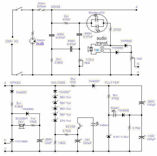
With this circuit you will be able to monitor the quality of the mains. There are 4 distinct sections, each supervising a parameter pertinent to the quality of the supply line. The noise section consists of a 50Hz filter...
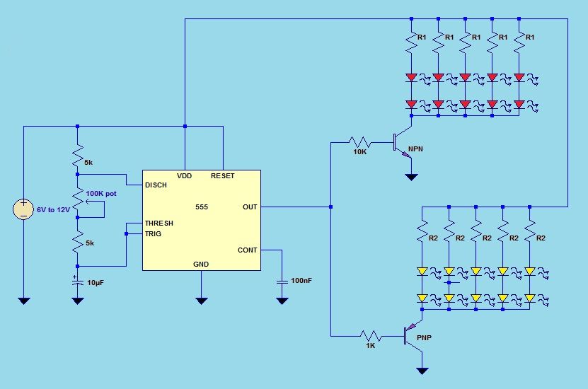
This project utilizes a 555 timer integrated circuit (IC) in an 8-pin configuration to control multiple LEDs. It is designed for quick assembly and allows for the adjustment of timing functions. The circuit employs a 555 timer in astable mode,...
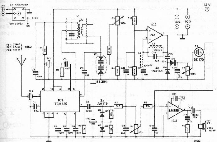
A simple FM CB radio receiver can be constructed using the electronic diagram provided. This FM CB radio receiver circuit utilizes a TCA440 integrated circuit and operates at an intermediate frequency of 455 kHz. The input filter is a...
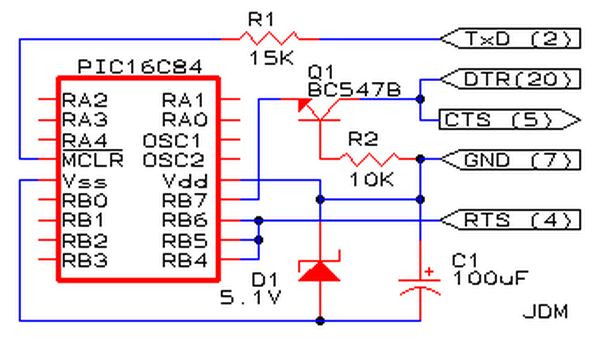
Affordable PIC Programmer. This programmer is compatible solely with the PIC16F84 microcontroller. It is reliable, as it rarely encounters errors, and functions well with nearly all computer systems, in contrast to some alternatives. The PIC programmer designed for the PIC16F84...
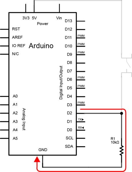
To create the circuit, connect a switch as an input and an LED as an output to the Arduino. The components required include a switch, an LED, a 10kΩ resistor, a 470Ω resistor, a blue or yellow jumper wire,...
Warning: include(partials/cookie-banner.php): Failed to open stream: Permission denied in /var/www/html/nextgr/view-circuit.php on line 713
Warning: include(): Failed opening 'partials/cookie-banner.php' for inclusion (include_path='.:/usr/share/php') in /var/www/html/nextgr/view-circuit.php on line 713