
Compact DJ Station

The mixer circuit comprises a robust design that allows for versatile audio input management and signal processing. The two stereo phono inputs are optimized for use with moving magnet cartridges, which are common in vinyl record players. The implementation of the LS4558 dual op-amp in the phono amplifier module ensures high fidelity audio reproduction with minimal noise and distortion, crucial for maintaining audio integrity during mixing. The RIAA equalization curve adherence guarantees that the frequency response of the phono stage compensates for the characteristics of vinyl playback, allowing for accurate sound reproduction.
The headphone amplifier module, based on the 5532 dual IC, is designed to provide sufficient output power for monitoring without introducing significant distortion, making it suitable for live sound applications or studio environments. The ability to deliver 50mW RMS into a 32 Ohm load ensures that the headphone output can drive a wide range of consumer headphones effectively.
The mixer features a user-friendly interface with dual gang log and linear potentiometers for precise level adjustments. The crossfader control allows for smooth transitions between audio channels, enhancing the mixing capabilities. The microphone input is designed to accommodate low impedance microphones, enabling vocal inputs to be seamlessly integrated into the mix. The adjustable gain on the main output ensures compatibility with various amplification systems.
Power supply options provide flexibility, allowing the mixer to be powered by either a 9V external adapter or a battery, enhancing its portability. The low current drain of approximately 13mA ensures long operational times when using battery power, making it ideal for mobile applications.
In summary, this mixer circuit is a comprehensive solution for audio mixing, featuring high-quality amplification, flexible input options, and user-friendly controls, making it suitable for both professional and amateur audio applications.The mixer features two stereo phono inputs and two stereo line-level inputs and has one stereo mixing channel. A microphone input and a stereo main output with adjustable gain are also provided. General Circuit diagram : all passive circuitry (controls, faders, switches, input and output connectors) is shown in full, whereas active amplification m
odules are represented by suitably labeled triangle symbols. Phono Amplifier Module : a high gain stereo amplifier suitable for moving magnet pick-up cartridges, having a frequency response according to RIAA equalization curve and based on the low noise, low distortion LS4558 dual IC. Two identical stereo modules of this type are required. Headphone Amplifier Module : this circuit was already present on this website under Portable 9V Headphone Amplifier.
It features a low current drain stereo amplifier based on the low distortion, low noise 5532 dual IC, capable of delivering 3. 6V peak-to-peak into 32 Ohm load at 9V supply (corresponding to 50mW RMS) with less than 0. 025% total harmonic distortion (1kHz & 10kHz). P1, P2, P4, P5_22K Dual gang Log Potentiometers P3_22K Dual gang Linear Potentiometer P6_22K Log Potentiometer R1 to R10_30K 1/4W 1% or 2% tolerance Resistors R11_1K 1/4W Resistor C1_2200 µF 25V Electrolytic Capacitor D1_3mm.
or 6mm. red LED J1 to J10_RCA audio input sockets J11_6mm. or 3. 5mm. Stereo Jack socket J12_6mm. or 3. 5mm. Mono Jack socket J13_Mini DC Power Socket SW1, SW2_DPDT toggle or slide Switches SW3_2 poles 3 ways Rotary Switch SW4_SPST toggle or slide Switch The input source can be selected by means of SW1 for Channel 1 and SW2 for Channel 2. Moving magnet pick-ups must be connected to Phono 1 and 2 inputs, whereas CD players, iPods, Tape recorders, PC Audio outputs and the like can be connected to Line 1 and 2 inputs.
After a separate Level control for each channel (P1 and P2), the two incoming audio signals are mixed and cross-faded by means of P3 and associated resistors network. The Crossfader control mixes both Channels at the same intensity when set in the middle position. When the cursor of P3 is fully rotated towards R3-R4, only Channel 1 signal is present at the Main output, whereas Channel 2 is muted.
Conversely, Channel 2 signal is present at the Main output and Channel 1 is muted when the cursor of P3 is fully rotated towards R1-R2. A low impedance microphone can be connected to the Mic input. P6 controls the signal level after amplification by the Microphone Amplifier module and feeds the Left and Right Mixer Amplifiers through R9-R10.
In this way, the speaker`s voice will be reproduced at the center of the soundstage. A stereo Headphone Amplifier with cue gain control is provided for monitoring purposes. The Cue Select switch SW3 will allow Headphone reproduction of Channel 1, Channel 2 or Master Channel, independently of the signal present at the Main Output. J13 is a Mini DC Power Socket into which the suitable plug of a 9V dc external supply adaptor should be inserted.
In any case, due to the low total current drain (about 13mA average), a 9V battery can be used satisfactorily to power the entire Station. R1, R10_2K2 1/4W Resistors R2, R3, R11, R12_100K 1/4W Resistors R4, R13_1K 1/4W Resistors R5, R6, R14, R15_18K 1/4W Resistors R7, R16_390K 1/4W Resistors R8_220R 1/4W Resistor R9, R17_10K 1/4W Resistors C1, C5, C6, C10_22 µF 25V Electrolytic Capacitors C2, C7_47 µF 25V Electrolytic Capacitors C3, C8_2n2 63V Polyester or Polystyrene low tolerance Capacitors C4, C9_10nF 63V Polyester or Polystyrene low tolerance Capacitors C11_100 µF 25V Electrolytic Capacitor IC1_LS4558 Dual High Performance Op-Amp A more strict RIAA equalization curve will be obtained if low tolerance components are used for R5, R6, R7, R14, R15, R16 (1% - 2%) and C3, C4, C8, C9 (2% - 5%).
🔗 External reference
Related Circuits
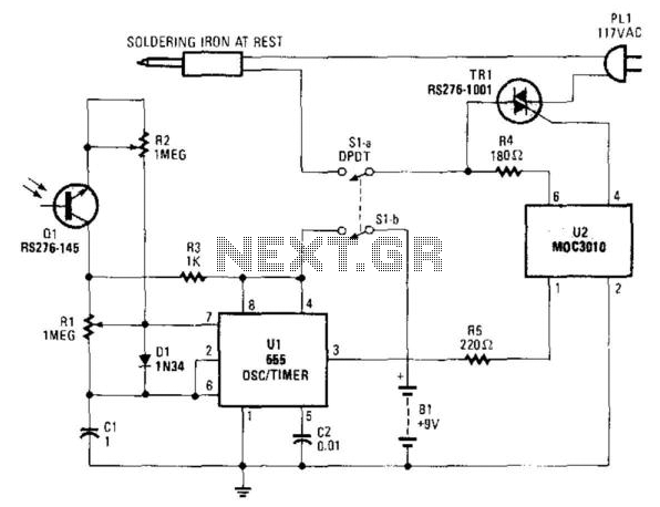
An infrared-sensitive phototransistor is employed to detect the temperature of a soldering iron. The phototransistor must be positioned to view the tip through an opaque tube to prevent interference from stray light, and it is advisable to equip the...
This hot-air rework station is suitable for professionals and hobbyists requiring precise temperature control and significant airflow. It features a digital display showing the actual air temperature, with a maximum flow rate of 23 liters per minute. This powerful...
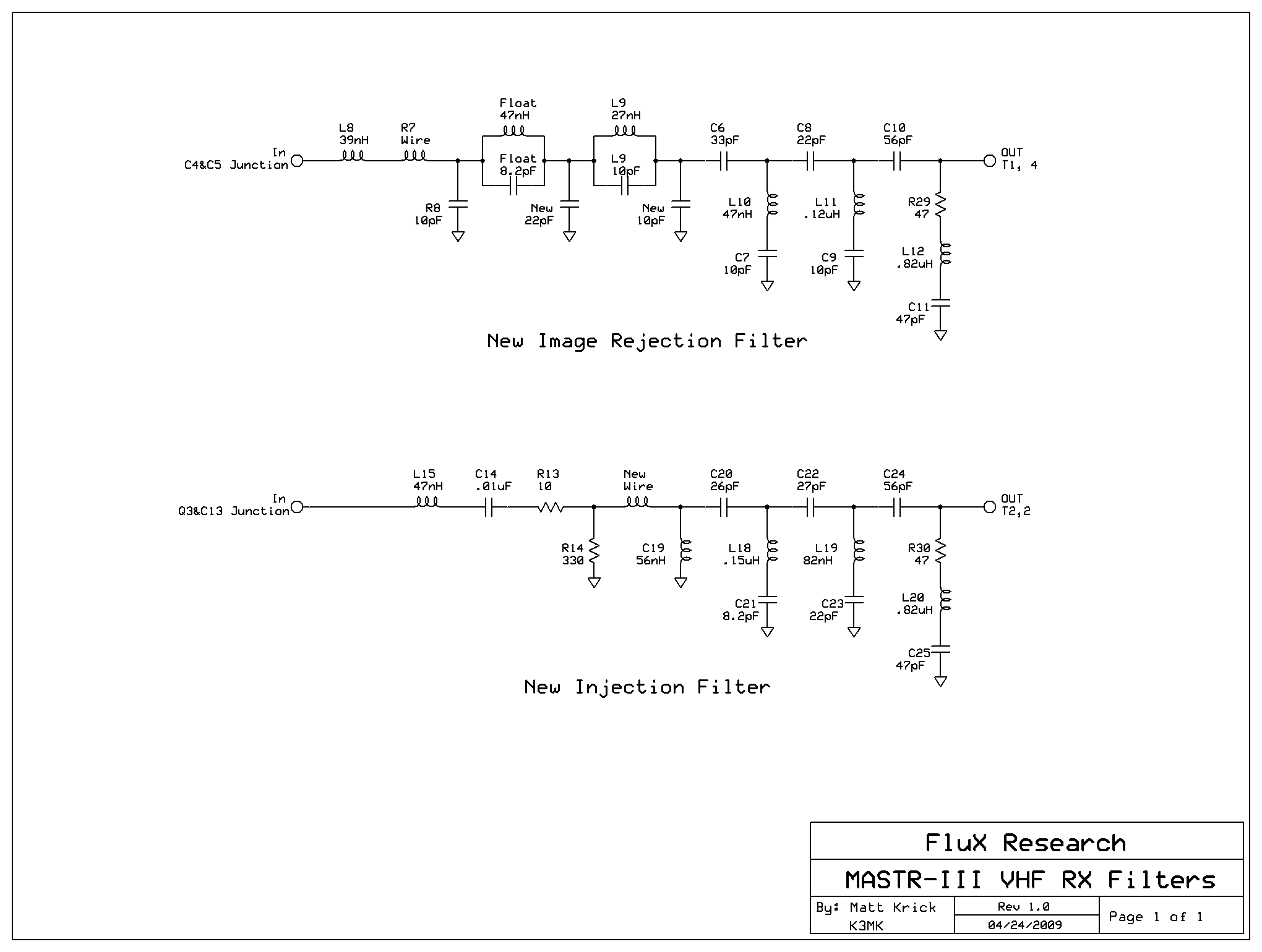
This article provides conversion instructions for radio model GE/MACOM MASTR-III Group 2 (150.8-174 MHz) Repeater or Base, Combination Number SXS, to enable it to operate effectively in the 144-148 MHz range. It is important to note that this document...
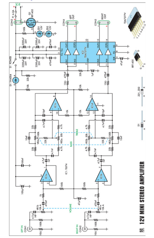
Amplifiers that operate on 12V DC typically do not deliver significant power and are often not classified as high-fidelity (hifi) devices. However, this compact stereo amplifier meets the power requirements effectively. This compact stereo amplifier is designed to operate efficiently...
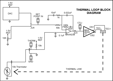
A compact thermal control solution for Dense Wavelength Division Multiplexing (DWDM) laser modules can be implemented using a MAX8520/21 and a single operational amplifier. The proposed thermal control solution utilizes the MAX8520 or MAX8521, which are highly efficient, low-dropout linear...
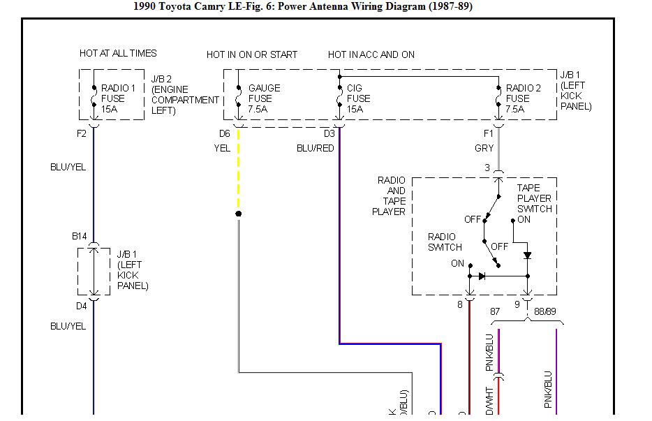
A 1990 Toyota Camry LE station wagon is being retrofitted with a replacement power antenna. The OEM antenna has been removed, but there is confusion regarding the connection of the new model, which has only two wires (red and...