
I have a 1990 Toyota Camry LE station wagon & trying to install

The replacement part's compatibility is in question. Resources such as Haynes and Chilton manuals have not proven helpful, and there is a desire to confirm whether the replacement part is suitable.
For the installation of the power antenna, it is essential to understand the configuration of the original wiring harness. The six wires in the OEM setup typically include power, ground, and control signals. In the case of the new antenna, the two wires (red and green) would generally represent the power supply and the control signal for the antenna motor.
To connect the new antenna, the following steps should be taken:
1. **Identify the Wires**: Use a multimeter to test the original wiring harness to identify the function of each wire. The power wire will usually provide a positive voltage, while the control wire will signal the antenna to retract or extend.
2. **Connect the Power Wire**: Connect the red wire from the new antenna to the power wire of the original harness. This wire should provide the necessary voltage to the antenna motor.
3. **Connect the Control Wire**: Connect the green wire from the new antenna to the control signal wire from the original harness. This connection will allow the antenna to respond to the vehicle's radio or switch.
4. **Ground Connection**: Ensure that there is a proper ground connection. If the OEM setup had a dedicated ground wire, it should be connected to the new antenna as well.
5. **Testing**: After making the connections, test the antenna operation by turning on the vehicle's radio or using the switch that controls the antenna. The antenna should extend and retract smoothly.
6. **Finalizing Installation**: Once the connections are verified and operational, secure all wiring to prevent movement and ensure that the antenna is properly mounted to avoid any mechanical issues.
In the absence of a limiter switch circuit, it is crucial to monitor the antenna operation to prevent any damage from overextension or retraction. If the replacement part does not function as expected, it may be necessary to consult with the manufacturer or consider alternative replacement options that include the necessary circuitry for proper operation.A 1990 Toyota Camry LE station wagon & trying to install a replacement power antenna. I have removed the OEM antenna (no easy task), but now trying to figure out how my replacement model that only has 2 wires (red & green) is suppose to connect with my original wiring plug (6 wires). Plus I have several wires that first connect to an OEM antenna control box before proceeding to the drive motor.
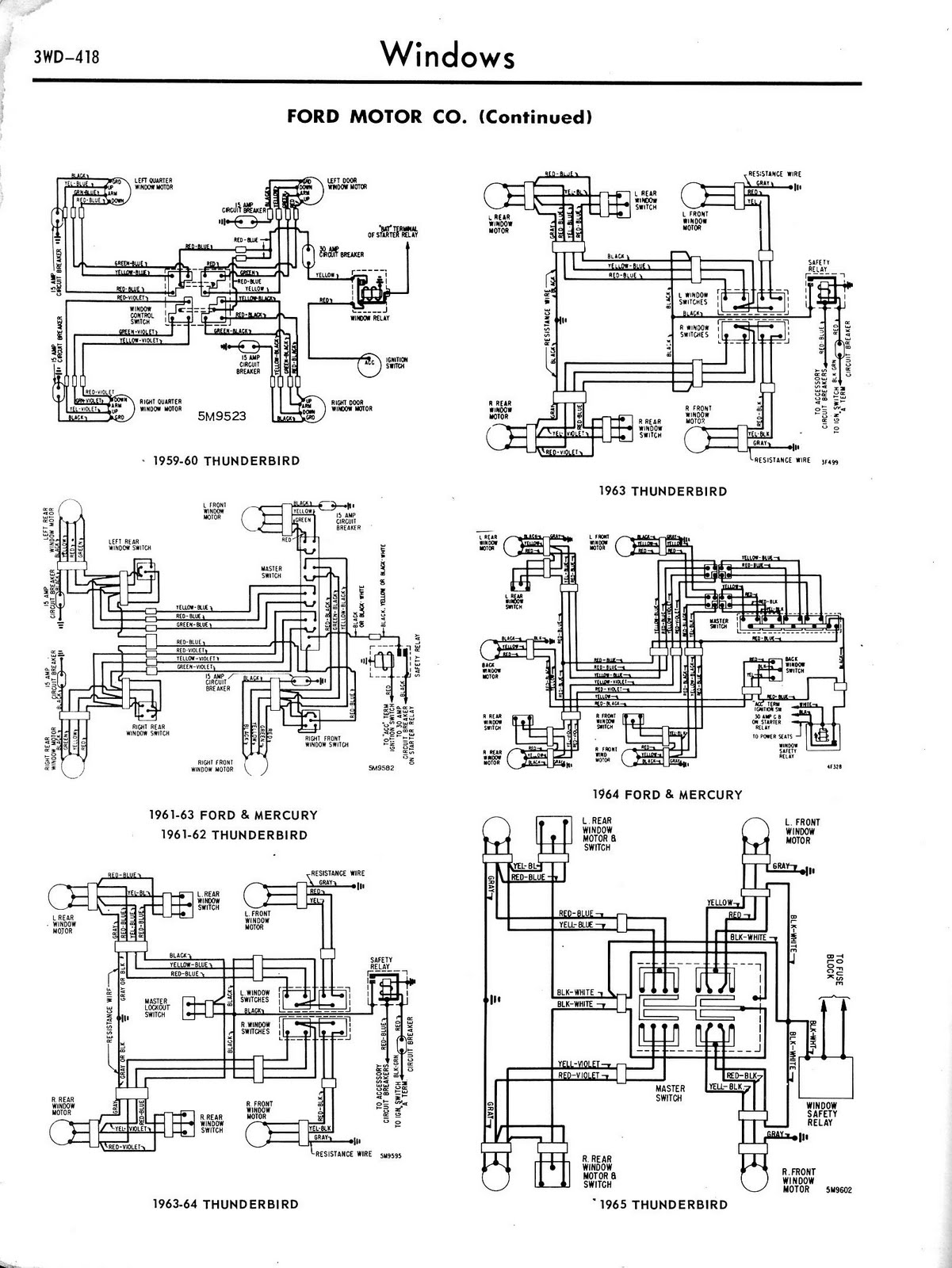
Looking for electrical installtion instructions ("Professional installation required" is the reply from replacement manufacturer given they included no instructions) plus a wiring schematic/illustration for the power anntena unit. I`ve checked Haynes & Chilton manuals - no help. I do have here the wiring schematic for your vehicle. The 2 wires from the motor should be for up and down depending on current flow. They should be connected to terminal 1 and 4. however with only 2 wires, there should not be a limiter switch circuit, it this replacement part the correct one Thanks AutoTech08 - I think your assistance & info is spot on.
However, llet me give your assistance a try & I`ll be right back with you in case I have any furhter questions Ask-a-doc Web sites: If you`ve got a quick question, you can try to get an answer from sites that say they have various specialists on hand to give quick answers. Justanswer. com. Traffic on JustAnswer rose 14 percent. and had nearly 400, 000 page views in 30 days. inquiries related to stress, high blood pressure, drinking and heart pain jumped 33 percent. THANK YOU, THANK YOU, THANK YOU! I`ve got my baby back. Tomorrow I will get a tank of high octane, remove the top, go for a long long ride and enjoy my car. THANK YOU! Jughead USA THANK YOU, THANK YOU, THANK YOU! I`ve got my baby back. Tomorrow I will get a tank of high octane, remove the top, go for a long long ride and enjoy my car. THANK YOU! Jughead USA Wonderful service, prompt, efficient, and accurate. Couldn`t have asked for more. I cannot thank you enough for your help. Mary C. Freshfield, Liverpool, UK This expert is wonderful. They truly know what they are talking about, and they actually care about you. They really helped put my nerves at ease. Thank you so much! Alex Los Angeles, CA Thank you for all your help. It is nice to know that this service is here for people like myself, who need answers fast and are not sure who to consult.
GP Hesperia, CA Just let me say that this encounter has been entirely professional and most helpful. I liked that I could ask additional questions and get answered in a very short turn around. Esther Woodstock, NY Thank you so much for taking your time and knowledge to support my concerns. Not only did you answer my questions, you even took it a step further with replying with more pertinent information I needed to know. Robin Elkton, Maryland 🔗 External reference
Related Circuits
Feed the cable through a hole in the chassis to the opposite side. There, between the fan and the rear panel, the IFD board can be installed upside down. Use a thin and flexible insulating material, such as PE...
The Link circuitry is simple and efficient, employing just two integrated circuits (ICs), a few transistors, and common components. It operates on 12 volts and is easy to assemble. This intercom system can connect various locations such as the...
Electrical lines that include lighting circuits originate from the main distribution panel of the installation. Each line consists of three conductors: phase, neutral, and ground. All three conductors extend to the terminal point of each luminaire, and if the...
The 4017 traffic light circuit connects four legs to the green LED and two legs to the amber LED. This configuration raises the question of whether it could function with only one leg per LED. Each output is activated...
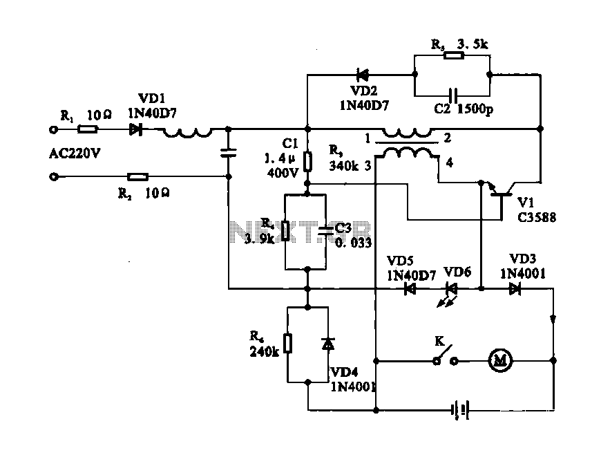
Electric shaver motor drive circuit. It illustrates a typical motor drive circuit for an electric shaver. AC 220V is used to charge the battery through the charging circuit, which also provides power to the motor. After activating the charge-on...
Toyota MR2 Exterior Lights Wiring Diagram Manual PDF Download. The Toyota MR2 Exterior Lights Wiring Diagram Manual provides a comprehensive guide for understanding the wiring configurations associated with the exterior lighting system of the Toyota MR2 model. This manual is...