
Compensation Resistor Stabilizes SMPS at High Duty Cycles

The implementation of current-controlled SMPS involves several critical design considerations. The stability of the power supply is paramount, especially when operating at high duty cycles. The introduction of slope compensation is essential to mitigate the risk of instability due to oscillations in the control loop. The slope compensation resistor, Rsl, is calculated based on the specific operational parameters of the SMPS, including the switching frequency and output characteristics.
In practical applications, the design may involve integrating the LTC3722-1 controller, which provides robust features for current-mode control. The internal current ramping source plays a vital role in generating the necessary slope for stable operation. The designer must ensure that the voltage pulse slope is adequately shaped to maintain stability across varying load conditions and duty cycles.
The analysis of the current ripple in the filter inductor, ΔiL, is crucial for determining the appropriate inductor size and type, which directly impacts the overall efficiency and performance of the SMPS. The choice of current-sensing resistor, Rcs, must also consider the current-limiting threshold, Vth, to prevent the system from entering a limiting mode under fault conditions.
In summary, current-controlled SMPS systems offer significant advantages in terms of stability and reliability, particularly when implemented with careful attention to slope compensation and current sensing. The design process requires a thorough understanding of the operational parameters and the interaction between various components within the circuit.Current-control switching-mode power supplies (SMPS) are gaining in popularity because they allow pulse-by-pulse current control and monitoring, making them more reliable and robust than their voltage-controlled counterparts. Current control also eliminates a positive zero in some transfer functions, which makes the supplies more stable.
However, at pulse duty cycles above 0. 5, current-control SMPS become unstable, oscillating at half of the switching frequency. 1 To stabilize the circuit, the designer must change the slope of the pulses going to the pulse-width modulation (PWM) comparator. 2 This can be done by adding a sawtooth voltage derived from the voltage across the timing capacitor to the voltage developed across the current-sensing resistor.
Or, you can add a high-enough current slope to the slope-shaping resistor before summing the voltage across the slope-shaping resistor and the current-sensing resistor in the current-sensing transformer`s output circuit. This idea describes how to compute the value of the slope compensation resistor, Rsl, that will create the desired voltage pulse slope.
The analysis uses Figure 1, which is part of a bridge converter that is a component of a current-control SMPS. Although the figure is a simplified schematic that denotes rectifiers as diodes and does not show the full bridge, it is suitable for this analysis.
1. This simplified schematic of part of a bridge converter that is a component of a current-control SMPS illustrates how designers can compute the value of a slope-compensation resistor to ensure stable operation. The voltage pulse slope is sent to the current-sensing input of U1, an LTC3722-1 synchronous dual-mode phase-modulated full-bridge controller with an internal current-ramping source whose peak current reaches 74 µA.
This internally generated current creates the compensation slope that adds to the slope of a pulse that is developed across the current sensing resistor, Rcs, making the current feedback loop stable at any duty cycle. The computation starts with the known factors: the SMPS output power, voltage, switching frequency, and other parameters that are obtained during the power supply analysis.
Assuming that the pulses across the secondary winding of transformer TR have an amplitude of Vsec, and neglecting the voltage drop across rectifier D2, which may be a synchronous low-dropout type: where D is the duty cycle of the rectified pulses. Note that Vload is not the rms value of Vsec. Then, the current ripple in the filter inductor, †iL, is: Assuming that the current transformer, TC, has one turn on the primary side and wct turns on the secondary, and the current-sensing resistor current is †ics: Sometimes, however, the IC`s current-sensing input has a current-limiting threshold, Vth.
If needed to avoid reaching the current-limiting mode, Rcs may be calculated using: If the controller IC that you employ does not provide the required current sawtoooth waveform, you can derive it from the voltage across the timing capacitor. Just add a simple power amplifier based on two complementary bipolar transistors. Good article Greg. Nicely done. But I don`t think you have spent much time working with current mode control on the bench. If you did, you`d have seen and then later derived in disbelief that the fast inside current loop in avg current mode or peak cmc removes one of the poles in the double pole filter formed by the output inductor and capacitor.
Further, it gives you a built in `feedforward` in that it corrects for input perturbations as fast as the pwm comparator can see the deviatiation in the V/L of the output filter inductor. Not actually a feedforward, but WAY quicker than the voltage loop. As for stability, yes, the academics will all agree that slope compensation is NEEDED to reset the ramp signal to the PWM at duty cycles above 50%.
it`s easy enough to draw that out on paper considering di/d 🔗 External reference
Related Circuits
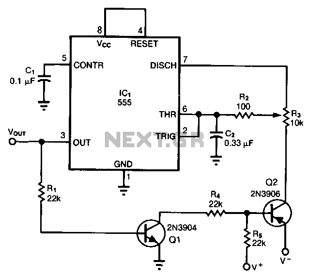
When configured as a free-running multivibrator, a 555 timer provides no more than a 50% duty cycle. By adding two transistors, however, it is possible to obtain a variable duty cycle ranging from 5% to 95% without altering the...
The half-linear design allows for reduced thermal considerations, as the linear regulator only needs to handle 1-5W instead of the full 75W per rail. MOSFETs operate in their linear region, just below the rated voltage for RDS(on), but they...
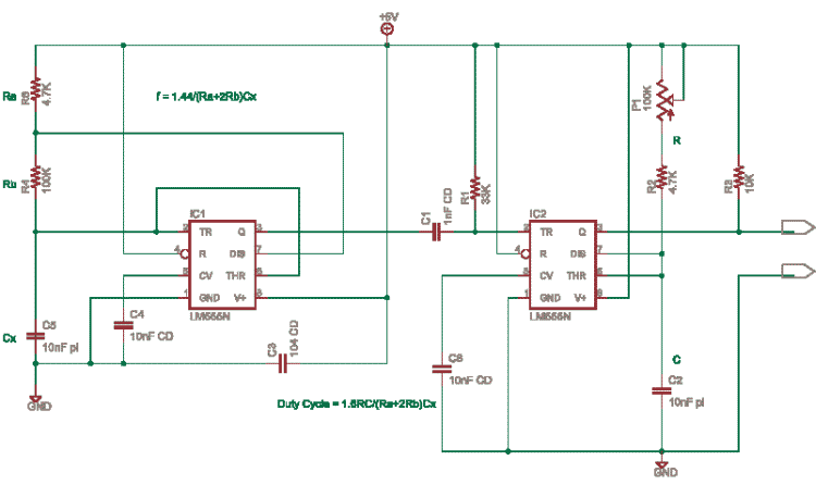
This circuit is based on an older application note from Exar. In this design, the frequency is determined by IC1, while IC2 and potentiometer P1 control the duty cycle. It is necessary to calculate the resistor (R) and capacitor...
A common telecoil follows the MM formula (magnetic-acting) and has an impedance of approximately 600 ohms to effectively receive signals. It is necessary to reduce the impedance in the high-frequency segment, which is achieved by placing a 150pF capacitor...
High-quality audio amplifier for computer circuit diagram. The electrical circuit of the amplifier is depicted in Fig. 1. The chosen integrated circuit for its construction is the TA8205AN, which is typically used in Hi-Fi applications due to its low...

The circuit described is a crystal oscillation circuit using a CM OS inverting configuration, designed to ensure accurate operation. It employs a BCD counter (IC2) capable of achieving a maximum oscillation frequency of 2 MHz, which is 100 times...