
Can produce circuits within the range of 1-99% duty cycle of the digital set-precision PWM wave

The crystal oscillation circuit utilizes a CMOS inverting configuration to maintain precise frequency control. The BCD counter (IC2) serves a critical role in generating clock pulses, with a maximum frequency of 2 MHz, which allows for a robust output even at a significantly lower target frequency of 20 kHz. This design choice ensures that the circuit can operate efficiently while providing a stable output.
The output from the BCD counter is utilized to generate a series of clock pulses, which are then fed into a flip-flop (IC7). The flip-flop's role is to maintain the state of the output based on the clock pulses received, ensuring that the timing of the output signal aligns with the desired frequency. The reset function is crucial for maintaining the integrity of the circuit's operation; it is triggered when the comparator (IC4,5) detects that the duty cycle has reached the predetermined set value.
The comparator monitors the duty cycle closely, ensuring that the output remains within the specified parameters. Once the clock pulse count concludes, the reset circuit is activated, allowing the system to return to its initial state and prepare for the next cycle of operation. This design achieves a resolution of 1% increments, thereby offering fine control over the duty cycle, which is essential for applications requiring high precision and stability. Overall, this circuit design exemplifies effective use of digital components to achieve a reliable and accurate oscillation frequency.Dien stone crystal oscillation circuit CM OS inverting clamor ways to ensure work as accurate because it uses a BCD counter Wong (IC2, hi) so maximum oscillation frequency equa ls 2MHz (100 times the required frequency of 20kHz) o assume IC, each output 100 clock pulses to trigger a flip-flop IC7 0 reset do j hit with a comparator IC (IC4,5) setting: a duty cycle reaches the set value, when the clock pulse count is terminated, reset circuit, so, IC., has set an output value equal to the duty cross-shaped. Resolution 1% increments, and very stable.
Related Circuits

This circuit was first introduced by Signetics Corporation as the SE555/NE555 around 1971. Pin connections and functions are as follows: Pin 1 (Ground) is the most negative supply potential of the device, typically connected to circuit common when powered...
A marker oscillator can be constructed using an NE555 timer to generate pulses at an audio frequency. This design facilitates the identification of signals amidst interference. The oscillator can utilize a crystal with a frequency ranging from 1 to...
This is a sine wave oscillator circuit, also known as an amplitude-stabilized sine-wave oscillator. It can provide a high purity sine wave output. The sine wave oscillator circuit is designed to generate a stable and high-quality sine wave output, which...
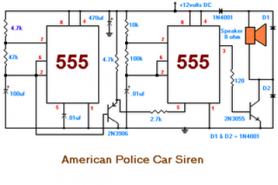
The second circuit simulates the siren of an American police car. It utilizes two 555 timers. The 555 timer on the right is configured as an alarm tone generator, while the second 555 timer on the left operates as...
Using only a single transistor and a few passive components, a fairly sensitive peak detector circuit can be built. This peak detector circuit is suitable for various applications. The peak detector circuit utilizes a single transistor, typically configured in a...
Current-controlled switching-mode power supplies (SMPS) are increasingly popular due to their ability to allow pulse-by-pulse current control and monitoring, enhancing reliability and robustness compared to voltage-controlled alternatives. Current control also removes a positive zero in certain transfer functions, contributing...