
fixed frequency with variable duty

The circuit utilizes the LM555 timer IC, a versatile component commonly used in various applications such as oscillators, timers, and pulse generators. In this configuration, IC1 is configured in astable mode, generating a continuous square wave output. The frequency of this output is determined by the values of the resistors and capacitors connected to the timer. Specifically, the frequency (f) can be calculated using the formula:
\[ f = \frac{1.44}{(R1 + 2R2)C} \]
where R1 and R2 are the resistors connected to the discharge and threshold pins, and C is the timing capacitor. The duty cycle, which is the proportion of time the signal is high versus the total period, can be adjusted using the potentiometer P1. This allows for fine-tuning of the output waveform to meet specific application requirements.
In designing the PCB, it is essential to consider the layout to minimize noise and ensure stable operation of the LM555. Proper placement of components, including decoupling capacitors near the power supply pins of the IC, will enhance performance and reliability. Additionally, ground planes should be utilized to reduce electromagnetic interference (EMI) and improve signal integrity.
For those interested in fabricating PCBs at home, various methods such as the toner transfer technique or using a CNC machine can be explored. However, for more complex designs or higher precision, outsourcing to a professional PCB manufacturer is recommended. This not only provides a higher quality product but also offers insights into the manufacturing process, which can be invaluable for future designs.
Overall, this circuit serves as an excellent foundation for learning about timer circuits and PCB design, encouraging experimentation and innovation in electronic applications.This circuit is based on a very old application note from exar, in this the frequency is fixed by IC1 and IC2 -P1 controls the duty cycle. you need to compute the R and C values to get what you need, LM555 data sheet. You have to study the circuit and do something more innovative perhaps, just copying is ok for learning but it will get you nowhere
, so learn and then innovate, the eagle circuit is given below so you can learn by editing it, also design a PCB with it, and you can even make a PCB at home to learn, but it is always good to get PCBs done by a PCB vendor, but you should understand his problems, then you will design well, so make a few PCBs. 🔗 External reference
Related Circuits
A simple method of charging a battery from a higher voltage battery is shown in the circuit below to the left. Only one resistor is needed to set the desired charging current and is calculated by dividing the difference...
This is a useful instrument for workshops. The standard of the produced frequencies is 10 to 1. The basic frequency is produced by a crystal with high accuracy. The circuit consists of the oscillator, around the crystal and the...
This circuit is a frequency doubler utilizing the 4011 IC. It employs a CMOS quad two-input NAND gate package, specifically the 4011. The circuit consists of two main components. The frequency doubler circuit using the 4011 NAND gate is designed...
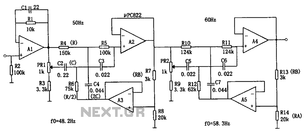
The circuit depicted in the figure is a frequency power supply noise filter circuit, specifically a double-T filter. It is designed to amplify weak signals, such as those from sensors, while filtering out mixed 50Hz (or 60Hz) power supply...
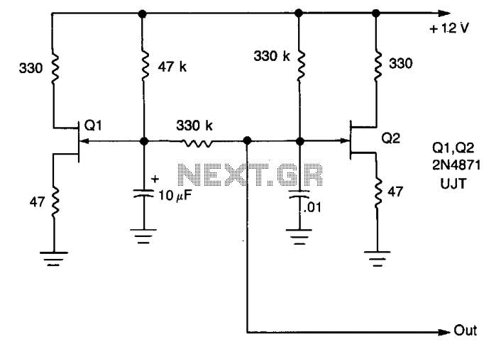
A low-frequency oscillator (Q1) modulates a high-frequency oscillator (Q2) along with its associated timing capacitor. The output frequency varies continuously. The circuit comprises two primary components: the low-frequency oscillator (Q1) and the high-frequency oscillator (Q2). The low-frequency oscillator is responsible...
Alternative display methods exist beyond the original 8 LED frequency counter, potentially offering improved readability and a more suitable format for QRP equipment. This document presents examples of binary decimal displays. Typically, the counter omits the MHz position, focusing...