
Complementary Power Amplifiers

The schematic described outlines a quasi-complementary amplifier circuit primarily constructed from components available at Radio Shack, focusing on simplicity and accessibility for hobbyists. The use of the IRF510 MOSFETs is particularly notable for their robustness and performance characteristics, making them suitable for audio amplification applications.
The differential phase splitter formed by the two JFETs is critical in ensuring that the amplifier can handle the input signal effectively, providing the necessary voltage gain to drive the output stage. The choice of JFETs, such as the MPF102 or 2N3819, is deliberate, as their specifications must align closely with the requirements of the circuit. The differential configuration allows for a mirrored output that enhances the overall voltage swing, contributing to the amplifier's efficiency.
The importance of the 330-ohm source resistor cannot be overstated. This resistor ensures that the signal flows correctly between the two stages of the amplifier. Bypassing this resistor would create a short circuit, leading to a malfunction of the amplifier. Therefore, it is imperative to maintain this component in the circuit.
Heat management is another critical aspect of the design, as the IRF510 MOSFETs can generate significant heat during operation. The suggested heat sinks should be adequately sized, painted flat black to improve thermal dissipation, and regularly checked to ensure that the MOSFETs remain at a safe operating temperature. This attention to thermal performance is essential for maintaining the longevity and reliability of the amplifier.
The second circuit's design, which doubles the output power, introduces additional complexity with the inclusion of four IRF510 MOSFETs. Ensuring that these devices are closely matched is vital for balanced performance, and testing each MOSFET in a low-current configuration helps achieve this goal. The parallel configuration effectively doubles the output current, allowing for greater power delivery to the load.
The addition of 470-ohm gate-stop resistors serves as a protective measure against high-frequency oscillations that could jeopardize the integrity of the circuit. These resistors are crucial for maintaining stability and preventing potential damage to the amplifier's components.
Overall, this schematic represents a practical approach to building a powerful audio amplifier using readily available components, emphasizing the importance of careful component selection, thermal management, and circuit stability.The first schematic is for those who never buy parts anywhere but Radio Shack. You can walk in the store and walk out with all the electronics that you need. For the heat sink, sorry to say, you`re on your own. Find a hardware store and buy a big chunk of aluminum. Saw the aluminum chunk into two pieces. Paint the aluminum pieces flat black. The p aint actually increases the magical powers of the heat sink. No kidding. Slather the transistors with silicon heat sink grease. Bolt each power MOSFET to its own piece of aluminum. Go in peace. Play loud. Sing until you steam up your bedroom or either a girl or the police show up. (If you`re a girl rocker, howdy! Beg pardon. If you`re a girl cop who plays rock music, cool. ) As I Promised, the first amp is as close to a Radio Shack-only circuit as I could come. This is a quasi-complementary circuit, because Radio Shack only sells an N-channel power MOSFET. We`ll use two of Radio Shack`s IRF510-type MOSFETs. Fortunately, the IRF510 is an excellent device. It`s exactly what we need: Rugged, sensitive and noncritical: A complete package. Phase Splitter. The two JFETs make up a differential phase splitter. I tried a one-device splitter, but it couldn`t put out enough voltage to get a big swing from the output MOSFETs. The two-device phase splitter also provides needed voltage gain. The JFETs are common types, such as MPF102 or 2N3819. (Only equivalent devices will work. Remember, these aren`t bipolar transistors. Unlike transistor specs, the IDSS and forward drop of FETs vary. ) In this quasi-complementary circuit, a differential phase splitter sends the original signal and its mirror to output MOSFETs Q3 and Q4.
Since the MOSFETs are in series, output peaks are higher than with a single-ended circuit. Source Resistor. In the Q1-Q2 circuit, don`t bypass the 330-ohm source resistor! Otherwise, the circuit won`t function. Your signal must pass from Q1 to Q2 across the source resistor. If you bypass this resistor, you`ll short out your signal! Use Heat Sinks on the two IRF510 MOSFETs. If the MOSFETs seem hot to the touch, then your heat sinks are inadequate. Increase the heat sink size. Paint the heat sinks flat black on both sides. (A lacquer magic marker will do just as well as paint. ) Play for awhile and check your transistors again. They must operate at about room temperature: That is, cool to slightly warm. If you can cook grits on a MOSFET, you`ll eat soon. But you won`t play for long. Twice the average power! This second circuit uses four drivers and doubles the average power. This quasi-complementary circuit is still not an earthshaker, but it`ll definitely rattle the bedsprings. Again, most of the parts come from Radio Shack. That includes all the FETs. Match the four IRF510 MOSFETs as closely as possible. To do that, breadboard a low-current test circuit. Then Try plug in each MOSFET in sequence. Each one must put out very close to the same drain voltage. Here, we`ve paralleled a second set of IRF510 MOSFETs with the first set. By Kirchoff`s Current Law, the parallel devices double the average output current. As in the first circuit, the 470-ohm gate-stop resistors discourage racing and VHF oscillations. The resistors are crucial. Oscillations could destroy the drivers. Use Heat Sinks on the four MOSFETs. You might need to adjust the value of the 330K bias resistors. Pots aren`t okay, because each one would adjust two parallel devices. If the two devices vary from one another, you still won`t achieve the ideal bias voltage! 🔗 External reference
Related Circuits
This article is intended for individuals interested in constructing their own car amplifier. The fundamental calculations will be discussed below. Understanding these concepts will enable the construction of a car amplifier independently. The challenge in designing a car power...
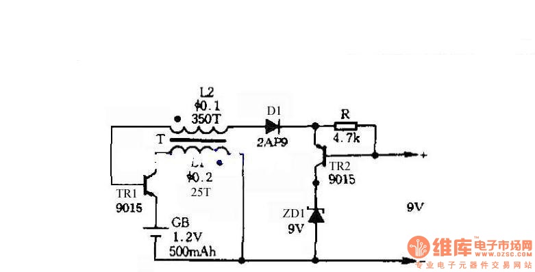
The circuit does not require a separate power switch or transformation to control the switches on the table. It offers advantages such as low power consumption, stability, reliability, and no impact on instrument accuracy. The transformer T in the...
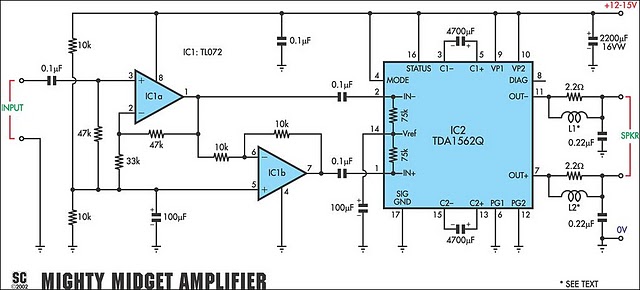
It is based on a Philips class-H audio amplifier IC and can deliver 36W RMS or 70W music power, all from a 13.8V supply. The Mighty Midget Amplifier can provide approximately 36W RMS continuous power into a 4-ohm load...
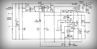
This is a low voltage, high-current output switching DC power supply with an input of 220 volts AC. In this circuit, an ST2 DIAC relaxation oscillator, Q3, C1, and the DIAC initiate conduction of the output switching transistor Q1....
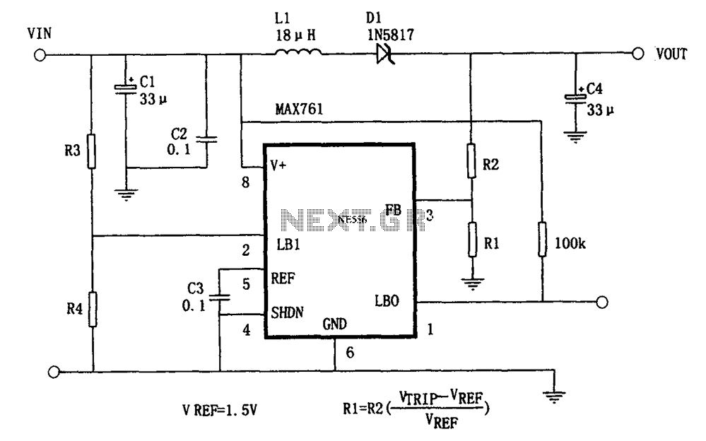
The circuit features an efficient, low-power output voltage boost DC-DC converter, MAX761, along with a few external components that facilitate adjustable power conversion. The output voltage is determined by the ratio of resistors R1 and R2, calculated using the...
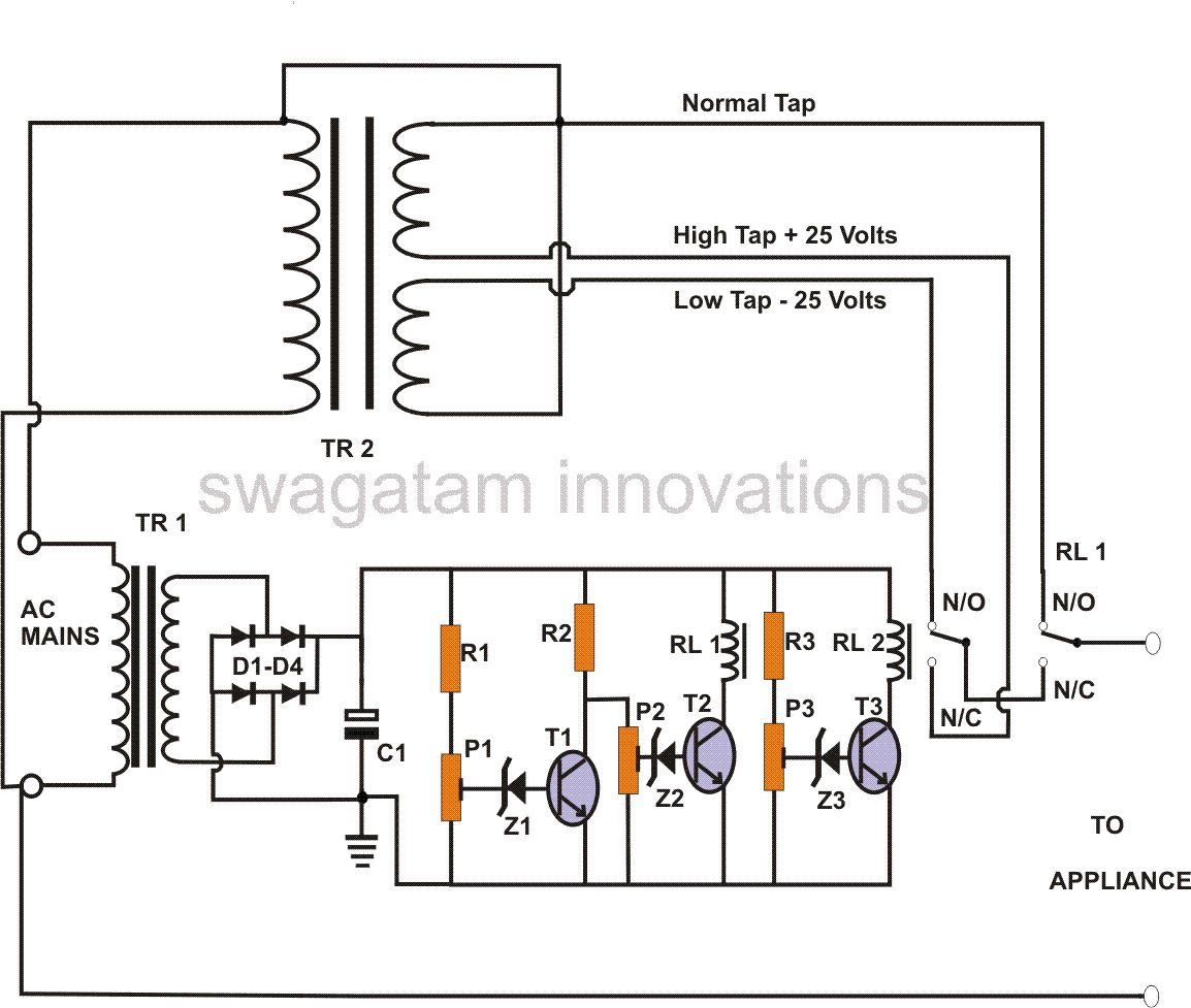
This power stabilizer circuit utilizes one relay to select either the high or low tap from the stabilizer transformer at a specific voltage level. The second relay maintains the normal mains voltage, but when a voltage fluctuation occurs, it...