
how to build 2 stage mains power
This power stabilizer circuit is designed to ensure the reliable operation of electrical appliances by maintaining stable voltage levels. The dual relay configuration allows for effective voltage regulation by automatically selecting the proper tap from the transformer based on real-time voltage conditions. The first relay's capability to switch between high and low voltage taps enables it to protect connected devices from damage due to voltage fluctuations. The second relay acts as a safeguard, ensuring that the output voltage is maintained within acceptable limits.
The use of transistors in this circuit adds to its efficiency and responsiveness. The transistors function as switches, controlling the relays based on the voltage detected at their respective inputs. The settings of the potentiometers (P1 and P3) allow for fine-tuning of the circuit, accommodating various appliances and their voltage tolerances.
The construction of the circuit involves careful attention to detail, particularly in the soldering of components and ensuring proper connections. The schematic serves as a critical reference throughout the assembly process, ensuring that each component is placed correctly to achieve optimal performance.
Once assembled, testing the circuit is essential to verify its functionality and reliability. This involves measuring the output voltage under different input conditions to ensure that the circuit responds appropriately to fluctuations. After successful testing, the circuit can be integrated with a suitable transformer, which will further enhance its performance by providing the necessary input voltage levels.
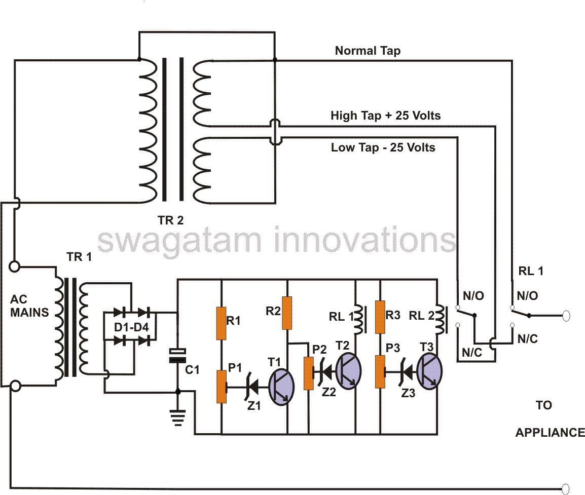
Finally, housing the completed circuit in a sturdy metal enclosure not only protects the components from physical damage but also minimizes electromagnetic interference, ensuring stable operation in various environments. The overall design and construction of this power stabilizer circuit exemplify a practical solution for voltage regulation, making it an invaluable addition to any electrical setup.In this power stabilizer circuit, one relay is wired to select the high or the low tap from the stabilizer transformer at some particular voltage level; whereas the second relay keeps the normal mains voltage switched in, but the moment there`s a voltage fluctuation it toggles and selects the appropriate HOT tap via the first relay contacts. A simple power stabilizer circuit discussed here is very easy to build and yet is able to provide a 2-stage correction of the input mains. A simple method of converting a normal transformer into a stabilizer transformer has also been discussed using circuit schematics. Basically the idea here is to make relay #1 switch at two different mains voltage extremes (high and low), which are considered not suitable for the appliances.
This switching enables this relay to select an appropriately conditioned voltage from another relay through its N/C contacts. The contacts of this second relay #2 makes it sure that it selects a appropriate voltages from the stabilizer transformer and keeps it ready for the relay #1 whenever it toggles during dangerous voltage levels.
At normal voltages, relay #1 remains activated and selects the normal voltage through its N/O contacts. As long as the voltage is normal, T1 stays switched off. Consequently T2 at this moment remains switched on. Relay #1 is activated, and its N/O contacts connect the NORMAL AC to the appliance. If the voltage tends to rise, T1 slowly conducts, and at a certain level (decided by the setting of P1), T1 fully conducts and shuts off T1 and relay #1.
The relay immediately connects the corrected (lowered) voltage supplied by relay #2 through its N/C contacts to the output. Now, in case of a low voltage T1 and T2 both will stop conducting, producing the same result as above, but this time the supplied voltage from relay #2 to relay #1 will be high, so that the output receives the required corrected level of voltage.
Relay #2 is energized by T3 at a particular voltage level (as per the setting of P3) in between the two voltage extremes. Its contacts are wired to the stabilizer transformer tapping so that it selects the desired voltage appropriately.
Begin the construction by inserting the transistors first, keeping ample space between them so that the other can be accommodated around each of them. Solder and cut off their leads. Next, insert the rest of the components and interlink them with each other and the transistors by soldering.
Take the help of the circuit schematic for their proper orientations and placements. The next page deals with the construction of the power stabilizer transformer and the testing procedure. After these procedures are completed, you may integrate the tested circuit assembly to the appropriate transformers.
The whole set up then may be housed inside a tough metal enclosure and installed for the desired operations. 🔗 External reference
Related Circuits
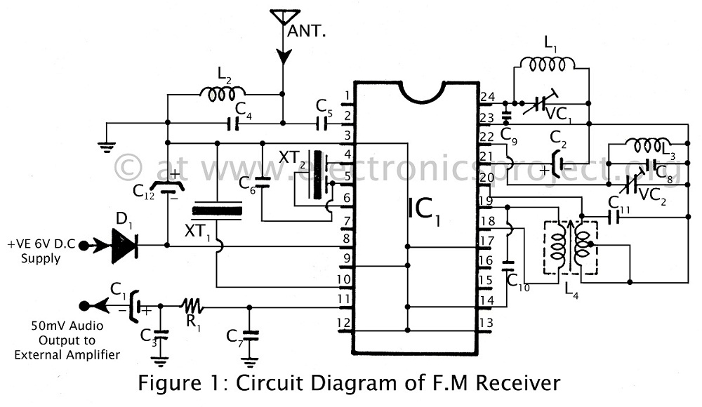
Communication in the FM band is straightforward. This circuit diagram illustrates a powerful FM receiver utilizing a single integrated circuit (IC) that receives frequencies from 88 MHz to 108 MHz within the FM band. The FM receiver circuit described operates...
There is a modification to the RC delay circuits that some may want to consider. If a shorter discharge time is desired, this modification enables the circuit to restart more quickly. The modification to the RC delay circuit involves adjusting...
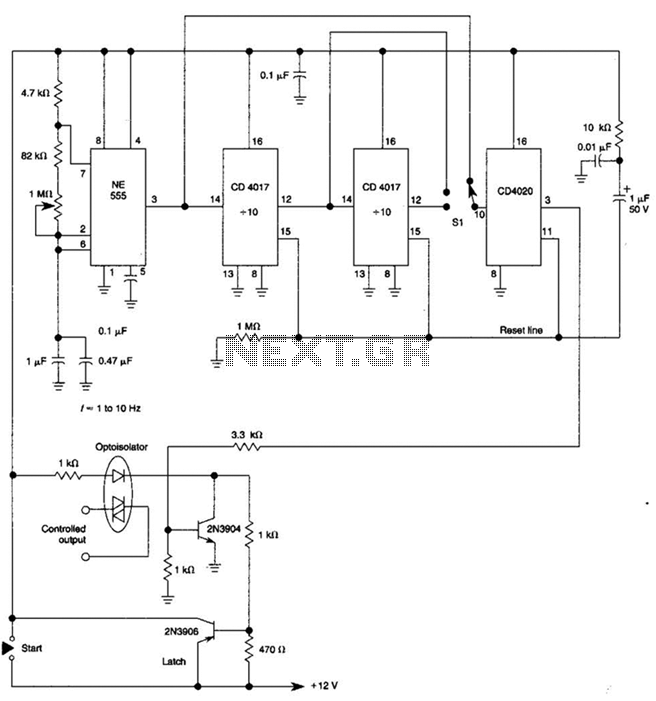
By using three 555 ICs, three sequential pulses can be generated. Output 3 can be connected back to the trigger input to achieve astable operation. The circuit described utilizes three 555 timer integrated circuits (ICs) configured to generate three sequential...
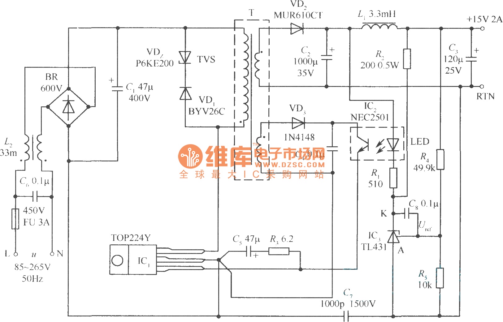
This document presents a 30W micro switch regulated power supply utilizing the TOP224Y integrated circuit. The circuit diagram illustrates its design. A notable feature of this power supply is the use of the TL431 component to replace the regulation...
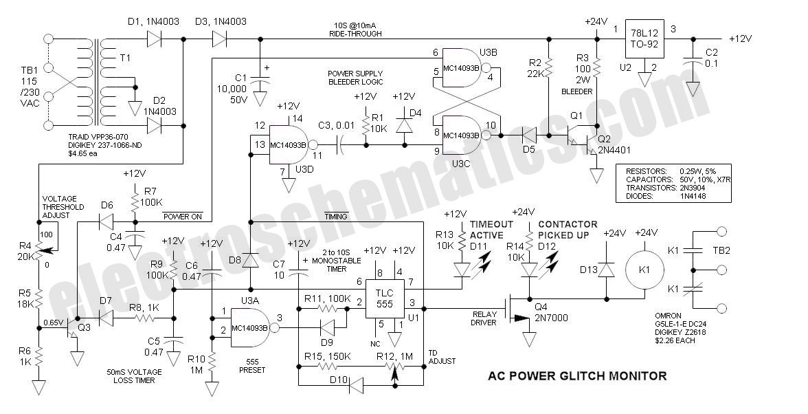
This AC Power Monitor continuously monitors the AC power line voltage for under-voltage conditions and missing cycles. When it detects a total of 5 or 6 consecutive anomalies, it triggers an alert. The AC Power Monitor is designed to provide...
The circuit employs a center-tapped transformer that steps down 230V AC or 110V AC to 9V-0-9V. Four 1N4001 diodes are utilized for the rectification of the AC voltage to DC. A 2200μF / 25V electrolytic capacitor is included to...