
Complete SS Laser Power Supply Schematics
The power supply circuit for pulsed solid-state lasers, particularly for configurations like PFN1, is a crucial aspect of laser technology. The design of such circuits must consider various parameters, including energy storage, pulse duration, and efficiency. The integration of high-quality components, such as the specified capacitor and inductor, directly influences the performance characteristics of the laser system. The automatic bleeder circuit is also essential for safety and reliability, ensuring that stored energy is safely dissipated when the system is not in operation. The flexibility in adapting these power supplies for different laser types highlights the versatility of solid-state laser technology. Careful attention to component selection, circuit layout, and safety protocols is paramount in the design and implementation of these power supplies to avoid risks associated with high voltage and energy levels. Overall, the understanding of pulse forming networks and their application in laser systems is fundamental for engineers and technicians working in the field of laser technology.This chapter contains circuit diagrams for several power supplies for pulsed solid state lasers. These include units suitable for driving the popular Hughes ruby and YAG rangefinder laser assemblies as well, one using the flash from a disposable pocket camera, and a high energy flashlamp power supply for that 8 inch long surplus NOVA laser rod you have been saving. :) The pulse forming network is what determines the performance of a pulsed solid state laser. Thus, there is a great deal of flexibility in the design of the capacitor charger and trigger circuits. Systems designed for other applications can often be adapted for solid state laser power supplies. See the chapter: SS Laser Power Supplies for more information. And the schematics in this chapter can be easily modified for larger, smaller, or different types of solid state lasers.
WARNING: All of these systems are potentially lethal - some just more lethal than others. Hey, but when you`re dead, it probably doesn`t matter how well done you are. Before even thinking about building or going near one of these systems, make sure you have thoroughly read, understand, and follow the laser and electrical safety guideline provided elsewhere in this document! PFN1 (manufacturer and model unidentified) is a combination of a 36 uF, 950 V energy storage capacitor, 0.
03 mH inductor, automatic bleeder circuit, and various connectors and other stuff. The capacitor is marked with its rating but the inductor is not and its value was determined by performing a `ring test` using both a separate high-Q 1 uF capacitor and then the one in the PFN. The original application for PFN1 was most likely to be used with the SSY1 laser head (see the section: A Small Nd:YAG Laser - SSY1 ).
The maximum useful energy into the flashlamp is around 14 to 15 J when charged to just over 900 V. Pulse Forming Network 1 shows the assembly with major components labeled. This unit is/was available from Meredith Instruments. When used without modification, the combination of the 36 uF capacitor and 0. 03 mH inductor will result in a 50 to 100 us pulse duration (dependent on other circuit parameters, probably closer to 100 us in practice). This is quite well matched to a Nd:YAG rod. With a well designed cavity, 15 J should be enough to threshold a 50 mm x 4 mm Nd:YAG rod (which is what it apparently was intended to pump) and considerably more than enough for a 25 mm rod.
Note that the capacitor in PFN1 is a very high quality non-electrolytic type. It may be a Polyester film capacitor with an ESR (Equivalent Series Resistance) of around 0. 02 Ohm (compared to almost 1 Ohm for a combination of electrolytic photoflash caps with the same uF and V ratings). The extremely low ESR is essential to achieve the required short pulse duration at reasonable efficiency (i.
e. , maximizing energy transfer to the flashlamp) or at all. Remove the other usable components from the PFN1 casting, unsolder the capacitor wire that goes through the base, and free up the other longer capacitor wire by breaking it free of the Epoxy globs fastening it in place and then tuck it out of the way so it won`t get damaged (e. g. , wrapped in a tight spiral on the end of the capacitor). Use a hack saw or rotary tool to slice the thin cast metal surrounding the capacitor just deep enough to reach the tough rubbery potting compound and no deeper.
This may have to be done in several places lengthwise, as well as around the base of the capacitor (next to where the other components were mounted). Then, carefully but persuasively pry the metal pieces from the potting compound leaving the capacitor stuck to the base.
It`s better to make some more cuts than to use a lot of force. It should be possible to peel the potting compound from the bottom of the capacitor but the adhesion there seems to be much stronger than to the yellow Mylar and it doesn`t look so bad left in place. :) This power sup 🔗 External reference
Related Circuits
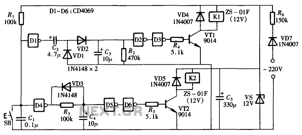
A one-button control switch is designed to control two relays, each of which can switch the load power on and off as needed. The circuit primarily consists of a hex inverter CD4049 and two self-locking DC relays. The circuit utilizes...
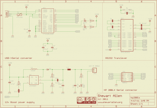
A personal digital assistant was introduced in 1994, often referred to as a palmtop computer. It was notable for being, with minor exceptions, an MS-DOS-compatible computer in a palmtop format. It featured a monochrome graphic display, a QWERTY keyboard,...
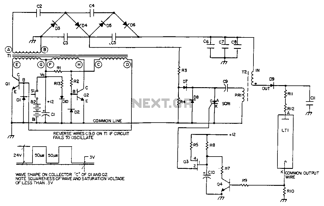
Q1 and Q2 control the primary windings of transformer T1 using a square wave at a frequency determined by the transformer's magnetic properties. Diodes D1 and D2 provide return paths for the feedback current of Q1 and Q2. The...
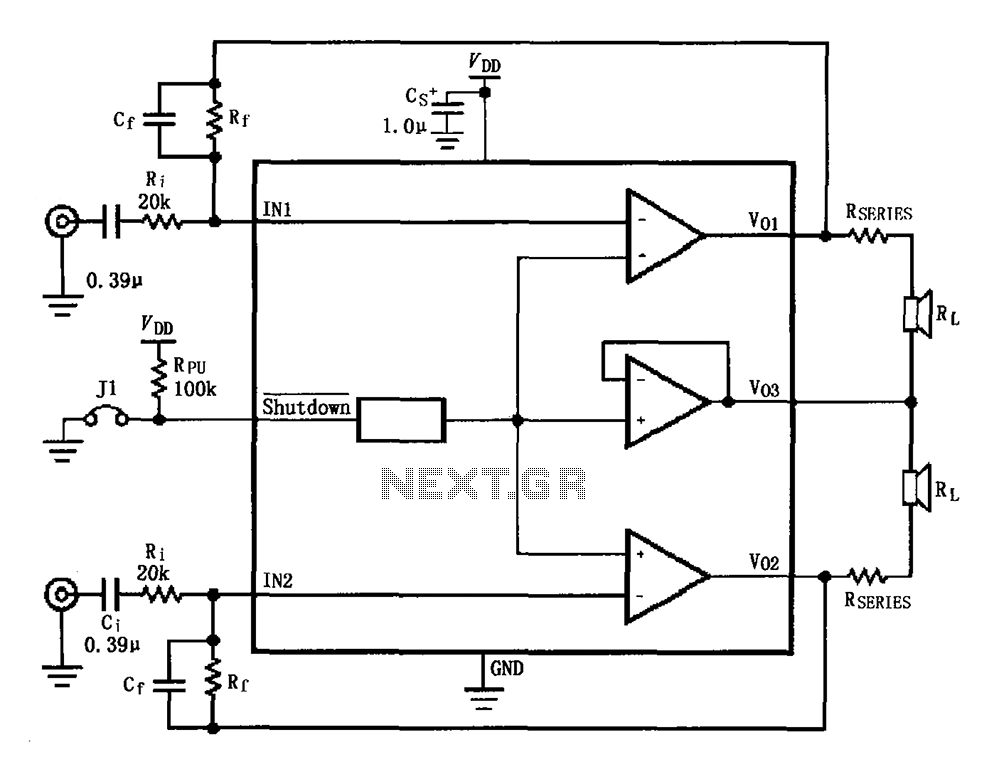
The circuit for the LM4910 is designed to minimize output noise and reduce power consumption. The output noise is attenuated by utilizing a resistor in series with the load. A feedback resistor Rf is used in conjunction with a...
This circuit can be adapted for other regulated and unregulated voltages by using different regulators and batteries. For a 15 Volt regulated supply use two 12 Volt batteries in series and a 7815 regulator. There is a lot of...
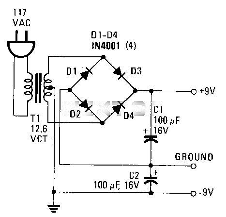
This power supply provides both +9 V and -9 V outputs to replace two 9-V batteries. The rectifier circuit consists of two separate full-wave rectifiers, each connected to the secondary winding of the transformer. The first full-wave rectifier, made...