
Morse Code Decoder Circuit
For those interested in becoming a HAM operator or holding a no-code license, there may be feelings of inadequacy without the traditional proficiency badge that distinguishes HAM operators from other radio users. Many individuals struggle with learning Morse code due to the challenge of decoding in real-time, where one must write down the last character while simultaneously listening for the next. Mistakes can disrupt the entire process, making it difficult to correct errors and leading to further missed characters. A potential solution to this dilemma is to eliminate the need to write down characters during the process of improving code speed. This requires a device that can copy and display the code in parallel, which is the intended function of the stand-alone device described in this article.
The decoder is designed to accommodate code speeds ranging from approximately 6 words per minute (WPM) to over 36 WPM. Its rate-adaptive algorithm quickly responds to changes in code speed, allowing users to copy both sides of a QSO, even if the transmitting parties operate at different rates. The schematic for the decoder is illustrated in figures 1a and 1b and consists of four major components, all powered by a set of four AA cells.
The first component is the front-end, which includes an electret microphone and a common emitter transistor amplifier. This section provides a wireless connection to either a radio receiver or a code practice oscillator. Depending on the specifications of the electret microphone used, the 15 kΩ resistor used for biasing may need adjustment. Besides amplifying the signal, the transistor amplifier also serves as a first-level bandpass filter, with its frequency response determined by the coupling capacitors and the feedback capacitor connected between the base and collector terminals of the transistor.
The second component is a narrowband Phase-Locked Loop (PLL) based tone detector, utilizing a tunable NE567 PLL tone decoder. The design follows the manufacturer's datasheet and incorporates hysteresis to prevent chatter, effectively debouncing the decoded signal. This narrowband detection capability allows for the discrimination of signals even when the target signal is significantly weaker than adjacent channel interference, provided there is a frequency separation of at least 100 Hz. The output from the detector generates a binary pattern that mirrors the DIT-DAH sequence of the incoming signal. This output is used to drive an input to the PIC16F84 microcontroller and also powers an LED, which serves as a tuning aid for the receiver.
The third component is the PIC16F84 microcontroller, which is responsible for measuring the duration of the one-zero input string received from the tone decoder and translating the pattern into a usable format. The design of the circuit ensures effective processing of the received Morse code signals, enhancing the user's ability to learn and improve their code proficiency.I have been getting a lot of emails about this project. Most of them are because of the bad source code listing at the end of the author`s notes. I have seen this problem all over the web and I too have ran into the same problem when compiling the code. I am assuming that the code has been copied and pasted so many times that things have been jumbled. You will notice that the code does not compile because of the duplicate labels "dlp1". I have not had time to fully break apart the code yet, but I am assuming the extra code that exists with the duplicate label is extraneous and should be removed. Once this block of code is removed, it should compile. I modified the code and reposted it. I also included the compiled hex file as well. NOTE: I changed the header to be used with the PIC16F84A since those are readily available from Microchip.
So you want to become a HAM, or you`ve got one of those no-code licences, but like me feel somewhat lacking, . not having obtaining that age old badge of proficiency that differientiated the HAM from other radio operators.
However, like thousands and thousands of others, you have trouble learning the code. The problem for most people is the non-real time nature of the process, i. e. , writing down the last character while listening to, and decoding the signature of the next character. Furthermore, when you make a mistake, the entire process collapses as your mind tries to perform error correction, trying to fill in the missing blanks, causing you to miss even more characters.
One way out of this delimma is to remove the burden of writing down the characters altogether during the process of building up your code speed. But to do this you need a device that copies and displays the code in parallel with you, which is what the stand-alone device described in this article is designed to perform.
The decoder is designed for code speeds ranging from about 6 words per minute (WPM) to greater than 36 WPM. The rate adaptive algorithm responds quickly to code speed changes, so you can copy both halves of a QSO, even when the parties transmit at different rates.
The schematic of the decoder is shown in figures 1a and 1b. It consists of four major pieces, all powered from a set of four (4) AA cells. The first piece, the front-end, is composed of an electret microphone and a common emitter transistor amplifier. This building block provides a wireless hookup to your radio receiver or code practice oscillator. The 15Kohm resistor biasing the electret may have to be changed to a different value, depending on the requirements of the electret you use.
In addition to providing gain, the transistor amplifier also acts as a first level bandpass filter. Its band edges are determined by the size of the coupling capacitors, and the feedback capacitor between Q1`s base and collector terminals. The second functional block is a narrowband PLL based tone detector, consisting of a tunable NE567 PLL tone decoder (Click here for the datasheet).
There`s nothing radical here, the circuit is right out of the manufacturers data sheet, and employs hysteresis for chatter prevention to, in effect, debounce the decoded signal. The small signal, narrowband detection capability of this block enables one to easily discriminate one signal from another, even when the signal you are copying is substantially smaller that the adjacent channel interference, as long as there is 100Hz or so frequency separation between them.
The output of the detector is a one-zero pattern replicating the DIT-DAH sequence of the received signal. This output drives both an input to the PIC16F84 microcontroller and an LED which is used as a receiver tuning aid.
More on that later. The third functional block is the PIC16F84 (Click here for the datasheet) microcontroller (CPU). Its function is to measure the duration of the one-zero input string from the tone decoder, and translate the pat 🔗 External reference
Related Circuits
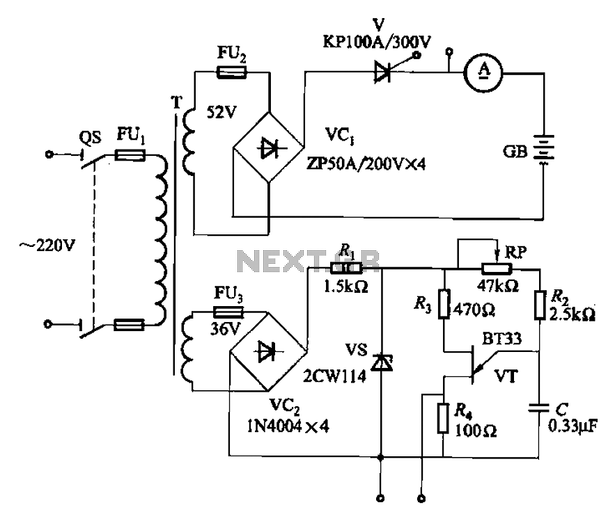
The adjustment potentiometer RP can modify the magnitude of the DC output voltage. The adjustment potentiometer, designated as RP, is an essential component in various electronic circuits, particularly in power supply systems and signal conditioning applications. It serves as a...
A crystal oscillator circuit is a straightforward oscillator circuit that can be easily understood through its schematic diagram. It serves as a replacement for a conventional oscillator network, which typically consists of an LC combination. This simplicity is also...
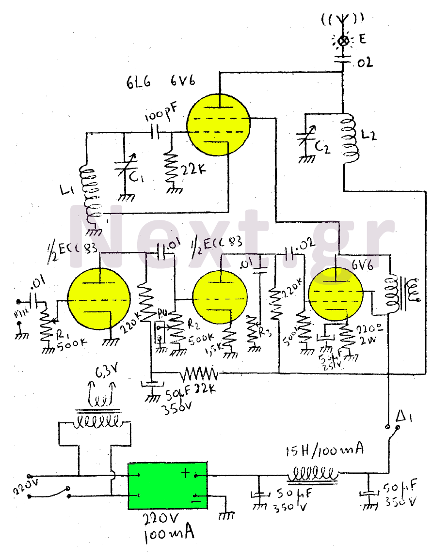
This circuit features a wearer assembly that includes a single lamp, either a 6V6 or 6L6, functioning as both an oscillator and an output amplifier. Coil L1 serves as the medium wave oscillation coil, while coil L2 is composed...
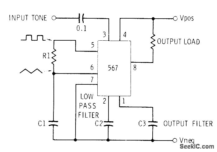
This circuit can be utilized for Touch-Tone decoding as well as for telephone line and wireless control applications using a single audio frequency. The operating center frequency is determined by components H1 and C1. The resistor R1 should be...
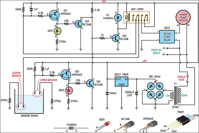
This circuit is designed to fill a header tank for a reticulated water supply on a farm. It serves eight troughs located in different paddocks, where a lack of water could have serious consequences for livestock. Previously, the tank...
The following circuit illustrates a simple stepper motor controller circuit diagram. This circuit is based on the 7404 integrated circuit. Features include suitable heat dissipation. The simple stepper motor controller circuit utilizes the 7404 hex inverter IC to control the...