
SH Hall opened with a double silicon output interface circuit
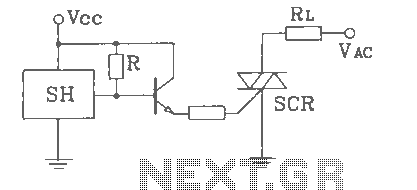
The SH Hall sensor circuit is designed to provide a dual silicon output interface, which enables enhanced signal processing capabilities. This circuit typically integrates a Hall effect sensor that detects magnetic fields and converts them into an electrical signal. The dual output feature allows for simultaneous monitoring or interfacing with multiple systems or components, improving versatility in applications such as motor control, position sensing, and proximity detection.
In the schematic, the Hall effect sensor is connected to a power supply, often a regulated voltage source, which powers the sensor. The output pins of the Hall sensor are configured to provide two separate signals, which can be either analog or digital, depending on the specific application requirements. The outputs may be interfaced with microcontrollers or other digital processing units, allowing for further manipulation and analysis of the sensor data.
Additional components may include resistors for signal conditioning, capacitors for noise filtering, and possibly operational amplifiers to enhance the output signals. The circuit may also incorporate protection diodes to safeguard against reverse polarity or voltage spikes, ensuring reliable operation in various environments.
The layout of the circuit should be designed to minimize electromagnetic interference (EMI) and maintain signal integrity, especially when the circuit is used in environments with strong magnetic fields or electrical noise. Proper grounding and shielding techniques are essential to achieve optimal performance and accuracy in the sensor's readings.
Overall, the SH Hall sensor circuit with a double silicon output interface is a robust solution for applications requiring precise magnetic field detection and processing, providing flexibility and reliability in electronic designs.SH Hall opened with a double silicon output interface circuit
Related Circuits

The phase and neutral wires from the power source have already been connected to electrical appliances such as fans and light points. According to the UPS connection diagram, an additional phase wire should be connected to those appliances where...
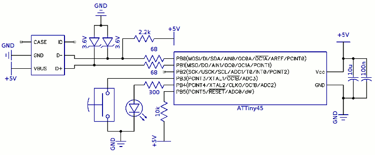
The project involves a trigger programming solution using a built-in pushbutton. The approach taken was to integrate a small USB keyboard circuit into the pen's interface. A proposed method for the pushbutton to trigger a programming command included adding...
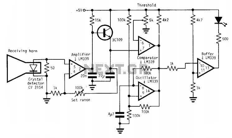
A simple X-band radar detector can indicate changes in RF radiation strength at levels as low as 2 mW/cm². When radiation strikes the detector diode, it generates a voltage at the input of an amplifier. The gain of this...
This document outlines the theory behind a high-speed control scheme for an LED display screen circuit. The circuit utilizes the MCS51 series microcontroller to manage the LED display. A 62512 random access memory (RAM) is employed for data storage,...
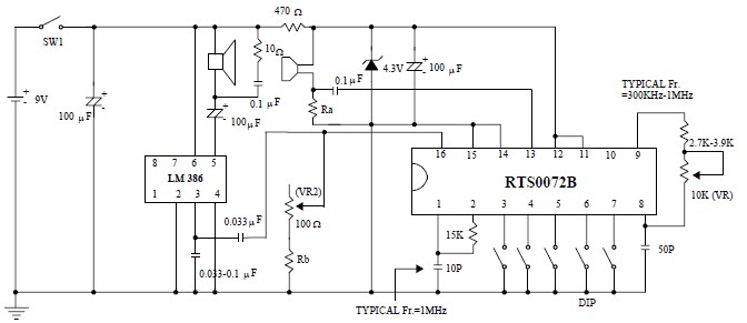
This voice changer circuit diagram is an electronic project developed using the RTS0072B single-chip CMOS LSI, specifically designed for voice-changing applications. It can transpose or distort one voice into another by encoding the input audio signals at normal speed...
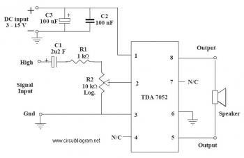
This is an audio amplifier circuit that uses the TDA7052 as the main component, along with five additional components to support its operation. The ideal supply voltage for this circuit is approximately 6-12V, and it does not require a...
Warning: include(partials/cookie-banner.php): Failed to open stream: Permission denied in /var/www/html/nextgr/view-circuit.php on line 713
Warning: include(): Failed opening 'partials/cookie-banner.php' for inclusion (include_path='.:/usr/share/php') in /var/www/html/nextgr/view-circuit.php on line 713