
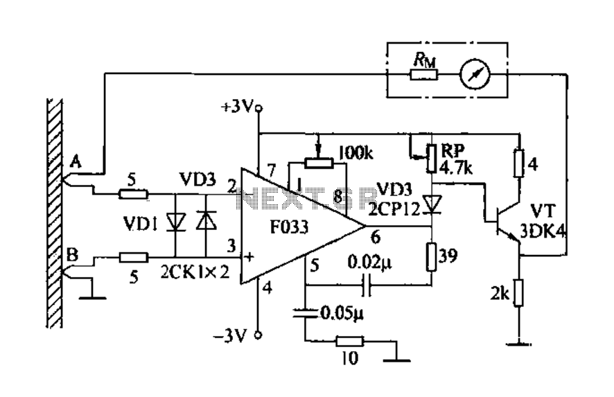
Diode Matching Circuit

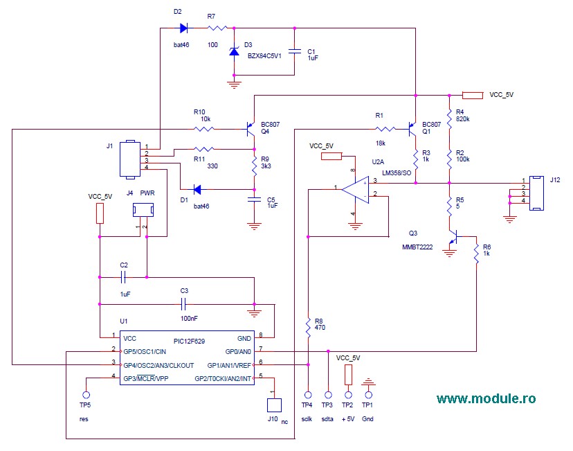
The diode matching circuit is designed to ensure that two diodes exhibit similar electrical characteristics, particularly their forward voltage drop. This is crucial in applications like balanced modulators, where mismatched diodes can lead to distortion and inefficiency in signal processing.
The circuit typically consists of a voltage source, a measurement device (such as a multimeter or an analog-to-digital converter), and the two diodes under test. The diodes are connected in a way that allows the forward voltage drop across each diode to be measured simultaneously.
In operation, the circuit applies a known forward bias voltage to both diodes. As current flows through the diodes, their individual forward voltage drops are measured. The circuit can be designed to display these values on an LED or LCD screen, providing a clear visual indication of the matching status.
Calibration is critical for accurate measurements; thus, the circuit may include adjustable resistors to fine-tune the voltage levels for precise readings. The output can be configured to indicate whether the diodes are matched within a specified tolerance, helping engineers select the most suitable components for their applications.
Overall, this diode matching circuit serves as a valuable tool in the design and testing of electronic systems, ensuring optimal performance and reliability in diode-dependent applications. This circuit can be used to match diodes for use in circuits where such a balance is necessary (a balanced modulator , for instance). The diode matching circuit will indicate the forward-voltage drop of the two diodes in millivolts.
Related Circuits
Detecting electrical equipment sometimes requires disconnecting the circuit in series for more accurate measurements of electrical current using an ammeter. However, restoring the circuit to its original state is necessary, as it can affect the normal operation of electrical...
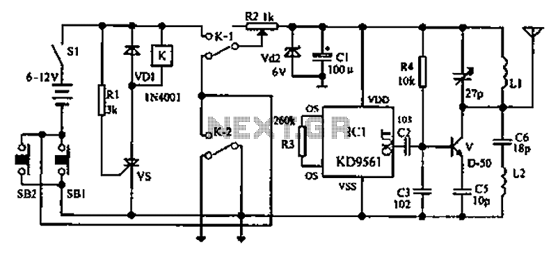
As environmental awareness increases, electric cars have become an essential part of people's transportation. Preventing electric car theft is a significant concern for owners. Various electric vehicle anti-theft locks have been developed; however, theft of electric cars continues to...
The motor control circuit depicted in the image utilizes the LM339 comparator among other components. When the input control signal is high (PWL), comparators A and A3 activate the power amplifier circuit, which consists of A4, VT5, and VT6,...
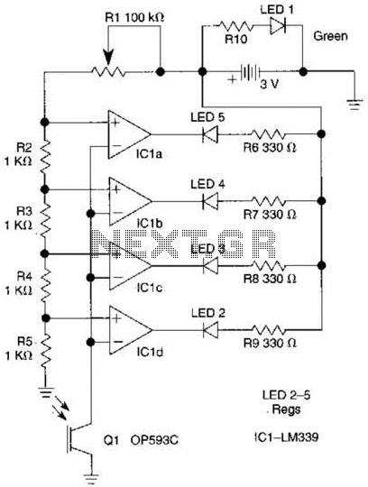
The outputs from the comparators will transition, in sequence, from high to low as the input voltage exceeds the reference voltage applied to each comparator. The output LEDs will activate sequentially as the voltage increases. The inverting inputs of...
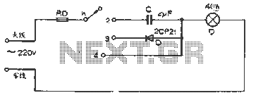
The figure illustrates a basic dimming lights circuit. The light intensity is controlled by a multi-speed control switch, designated as K. When switch K is set to position "1," the lights are turned off. In position "2," the light...
Unlike most surface-mounted device (SMD) resistors, SMD ceramic capacitors do not have their values marked. To determine the value of these capacitors, a capacitance meter is required. SMD ceramic capacitors are widely used in modern electronic circuits due to their...