
compressor microphone

The FM Remote Control Receiver circuit is designed to facilitate audio transmission in intercom and public address applications by providing a reliable analogue output signal. The integration of the CA3080 OTA allows for effective signal amplification while maintaining low noise levels, which is critical for clear audio reproduction. The choice of a 5 V supply ensures compatibility with a wide range of transmitter modules, making the circuit versatile and easy to implement in various applications.
The TS924IN quad operational amplifier is employed in this design due to its rail-to-rail output capability, enabling the circuit to operate effectively across the entire voltage range. The filter configuration, designed as a 3rd order Chebyshev filter, is specifically tailored to enhance the clarity of speech by reducing unwanted frequencies and allowing for a turnover frequency of 5.5 kHz. This frequency adjustment is crucial for maintaining intelligibility in speech, especially in environments with background noise.
The feedback mechanism implemented via peak rectifier D1 and capacitor C3 ensures that the OTA operates within optimal parameters, stabilizing the gain and preventing distortion at low signal levels. The adjustment capability offered by potentiometer P1 provides flexibility for users to fine-tune the amplifier's response based on specific application requirements, allowing for a balance between fixed gain and dynamic compression.
Overall, this circuit design exemplifies an effective approach to building a microphone pre-amplifier suitable for intercom and public address systems, emphasizing the importance of component selection, filter design, and feedback mechanisms in achieving high-quality audio performance.The FM Remote Control Receiver` (available on this website in Infra-red circuits section) has a connector where an analogue output is made available. To make a simple intercom or P. A. system the associated transmitter needs a microphone pre-amplifier that outputs a signal at the correct level.
And that is exactly the function of this circuit. Act ually, this design is adapted from a circuit published last year (AM Modulator for Intercom`). A few things have been changed so that it can work with the 5 V supply from the transmitter module. The OTA (IC1) used here is the single version (CA3080), which has slightly different characteristics from the dual CA3280. The quad opamp is the same rail-to-rail TS924IN, made by ST. The turnover frequency of thelter (3rd order 1 dB Chebyshev) has been increased slightly to improve the intelligibility of speech and is now about 5.
5 kHz. Thelter now amplies the signal by a factor of 10. In practice it is possible that due to various tolerances and the fact that the opamp is not perfect, thelter characteristic shows some deviation from that required. In our prototype it was necessary to change R15 into 2k7 to straighten the response curve. The DC current variation at the output of the OTA and the resulting offset variation at the output of current/voltage converter IC2d is such that the gain of IC2d has to be substantially smaller than in the old` design.
Otherwise the output could easily rise to the supply voltage at low signal levels. The value of R6 has therefore been made smaller by a factor of 10. This has reduced the gain of the circuit by 20 dB, which is compensated for in thelter. The amplitude of the signal from IC2d is fed back as a control current to the OTA by peak rectier D1/C3 and inverting amplier IC2b. R7 limits the loading on IC2d. P1 can be used to adjust the amplifier between a fixed gain and maximum compression. shows clearly what effect the circuit has. 0 dBr corresponds to 100 mV. The maximum gain, with P1 set to maximum compression, is about 48 dB (250 ©) for small signals. 🔗 External reference
Related Circuits
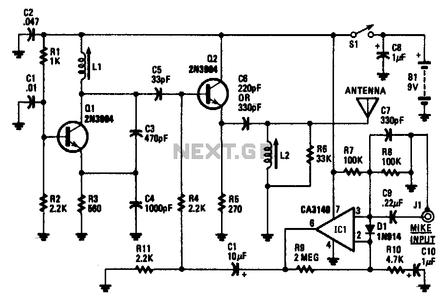
The transistor Q1 and its associated components form a tunable RF oscillator. The RF signal is directed to transistor Q2, which functions as the modulator. Operational amplifier IC1 amplifies the audio signal and transmits it through resistor R4 to...
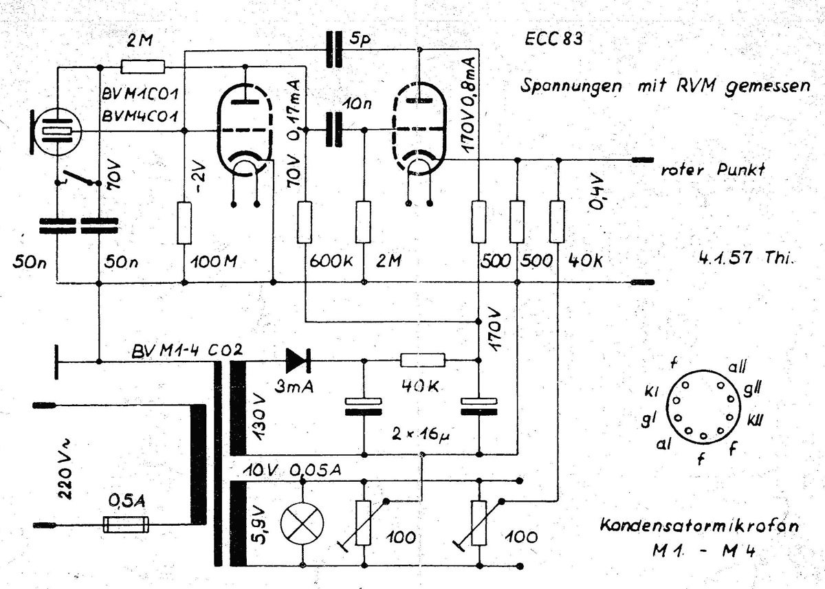
The power supply is integrated into the base of the microphone, which may cause hum issues, even with the onboard potentiometer designed to nullify this effect. Consequently, the microphone features two cables: one for power and another for audio...
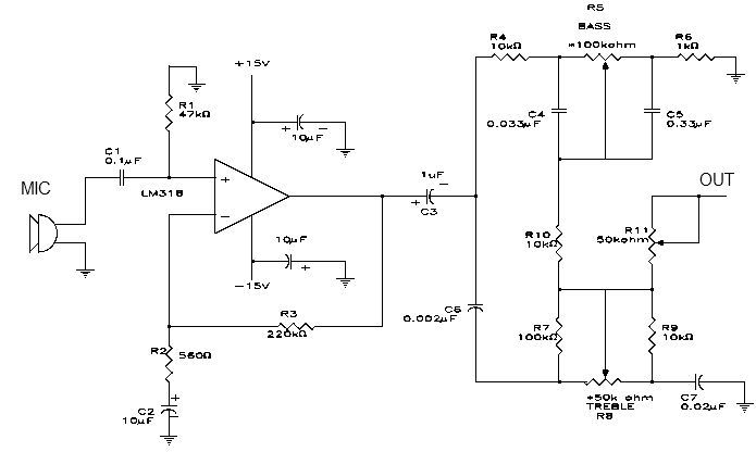
This simple microphone preamplifier is based on the LM318 operational amplifier. The LM318 operates as a standard non-inverting amplifier. Resistor R1 provides a ground input path for the bias current of the non-inverting input. The combination of R2 and...
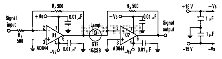
Designers can construct a 15-dB compressor using a miniature lamp and a current-feedback amplifier. The circuit exhibits extremely low distortion at frequencies above the lamp's thermal time constant, indicating that distortion remains negligible from audio frequencies to over 10...
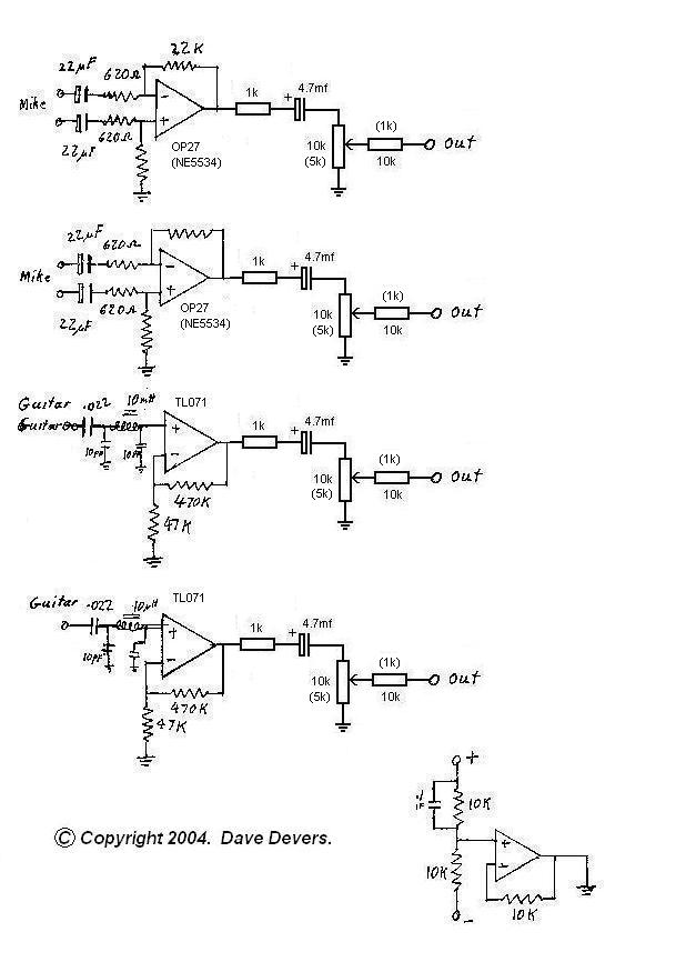
The mixer is extremely useful for direct input (DI) of guitars and basses into soundcards or other mixers, allowing for the utilization of channels on mixers that lack microphone inputs. It is particularly beneficial for one or two guitarists...
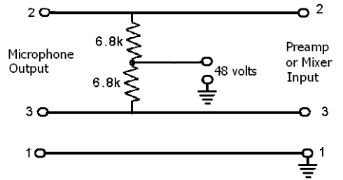
These devices require power to operate. This power can be supplied by a battery inserted into the microphone, a separate dedicated power supply with a specialized multi-pin cable, or most commonly, phantom power. Phantom power is supplied by a...