
RS-232 surge protection
Overvoltage protection circuits are essential in safeguarding sensitive electronic components, particularly in data communication applications such as RS-232C serial ports. The primary function of these circuits is to prevent excessive voltage levels from damaging the connected devices.
A typical overvoltage protection circuit may include components such as zener diodes, transient voltage suppressors (TVS), and series resistors. Zener diodes can be employed to clamp the voltage to a specific level, thereby preventing it from exceeding the maximum ratings of the connected components. The zener diode should be selected based on the maximum allowable voltage for the device being protected.
Transient voltage suppressors offer rapid response to voltage spikes, making them suitable for protecting against transient overvoltages. In addition, series resistors can be included to limit the current flowing through the circuit during an overvoltage event, providing an additional layer of protection.
The construction of the circuit is equally important. Proper layout techniques, such as minimizing trace lengths and ensuring adequate grounding, can significantly enhance the effectiveness of the overvoltage protection. Components should be positioned to minimize inductance and capacitance, which can affect the circuit’s response time.
For those who require a higher level of reliability and performance, commercial overvoltage protection units from reputable manufacturers are recommended. These units are designed to meet stringent standards and are tested for performance, providing peace of mind in critical applications.
In summary, implementing an effective overvoltage protection circuit involves careful selection of components and attention to construction details. By doing so, the longevity and reliability of sensitive electronic devices, particularly in communication applications, can be significantly improved.The following circuit are provded here to give your idea how the overvoltage protecton circuits really work and how you can easily add some protection to your circuits. To make theose circuit really effective need careful component choosing and good construction. For best performace I recommend using commercial units from realiable data communication product manufacturers.
RS-232C serial port lines are quite prone to be damaged by overvoltages. The damaged to computer serial ports have become more and more expensive to replace because of higher intergaration: usually you have to buy new motherboard if one serial port in it 🔗 External reference
Related Circuits
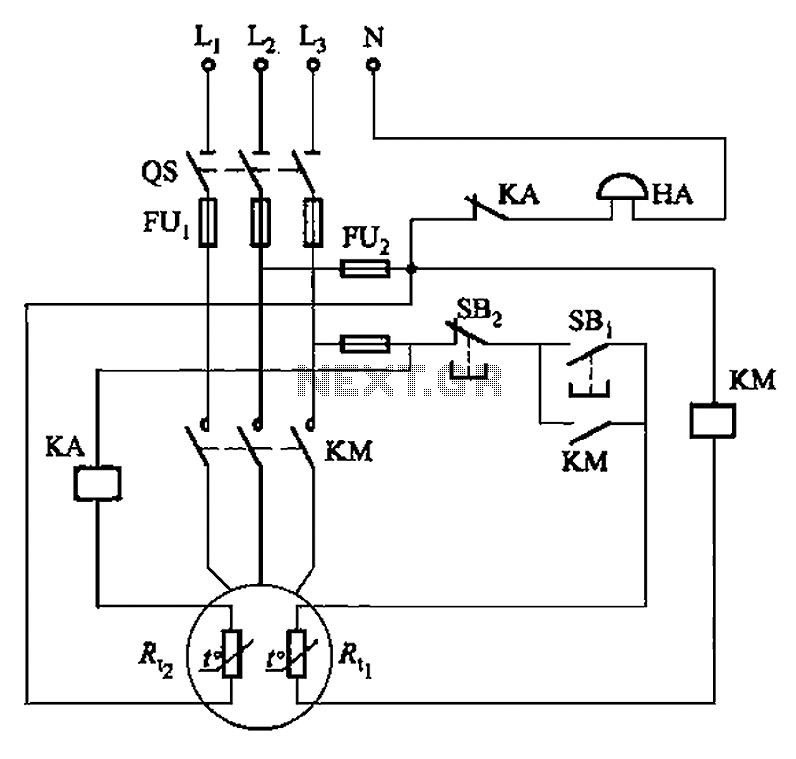
The circuit illustrated in Figure 4-2 employs two thermal resistors. One, designated as Rc, functions as overload protection, while the other, labeled Rt, serves as an alarm. The circuit in question integrates two thermal resistors to monitor temperature changes and...
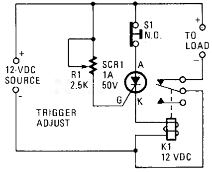
A silicon-controlled rectifier (SCR) is connected in parallel with the 12-V line and linked to a normally-closed 12-V relay, designated as K1. The gate circuit of the SCR is utilized to monitor the applied voltage. While the applied voltage...
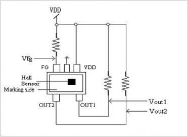
The XC6119 series is a highly precise, low power consumption voltage detector, manufactured using CMOS and laser trimming technologies. The device includes a built-in delay circuit. A release delay time can be set freely by connecting an external delay...
Power supplies designed for use with TTL logic circuitry must protect against over-voltage, which can rapidly damage TTL chips. The duration of over-voltage that can harm TTL chips is too short to activate any conventional fuse, necessitating the use...
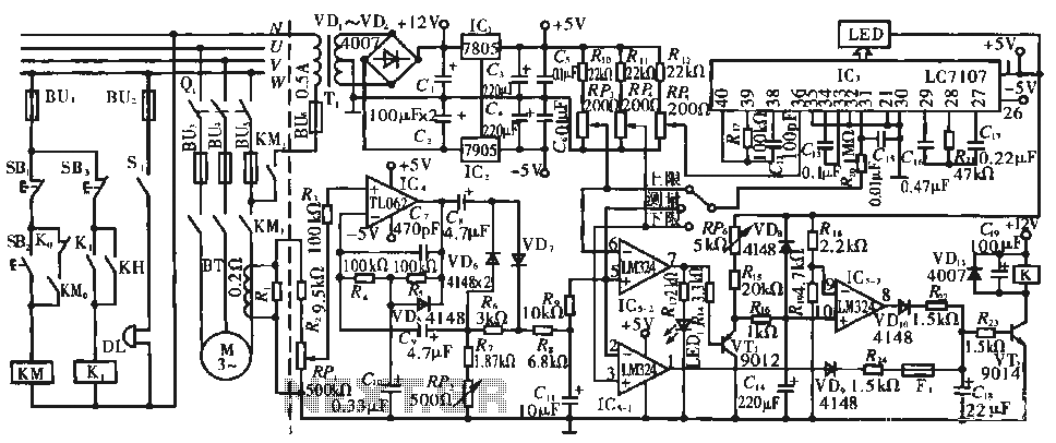
The circuit operates during standard inspection work by utilizing the voltage across resistor R2, which is connected to RP, to generate the input signal for IC4. Components R3 through Rg, along with capacitors C7 and C1, and diodes VD7...
In applications where a MOSFET is employed to switch a load, incorporating short-circuit or overload protection is straightforward. This can be achieved by utilizing the internal resistance RDS(ON) of the MOSFET, which generates a voltage drop proportional to the...