
Short Circuit Protection With A MOSFET
In the described circuit, the MOSFET operates as a switch for the load, with its internal resistance RDS(ON) serving as a means to detect current levels. The voltage drop across RDS(ON) is directly proportional to the current flowing through the MOSFET, allowing for effective monitoring of the load conditions. The comparator is set to trigger at a threshold voltage of around 0.5V, which corresponds to a specific current limit that indicates an overload condition.
When the voltage across RDS(ON) exceeds this threshold, the comparator activates, signaling the microcontroller to implement protective measures. These measures can include adjusting the PWM signal driving the MOSFET to reduce the load current, activating an alarm to alert users, or initiating an emergency stop to disconnect the load entirely. This layered approach to overload protection enhances system reliability and safety.
Furthermore, connecting the comparator output directly to the MOSFET gate allows for immediate response to short-circuit events. When a short circuit occurs, the rapid increase in current causes the voltage across RDS(ON) to rise quickly, triggering the comparator. This action results in the MOSFET being turned off almost instantaneously, thereby protecting the circuit from potential damage.
Overall, this design leverages the inherent properties of the MOSFET and simple components to create an efficient and effective overload and short-circuit protection mechanism, enhancing the robustness of electronic applications that rely on MOSFET switching.If you have an application in which a MOSFET is already used to switch a load, it is relatively easy to add short-circuit or overload protection. Here we make use of the internal resistance RDS(ON), which produces a voltage drop that depends on the amount of current flowing through the MOSFET.
The voltage across the internal resistance can be sensed using simple comparator or even a transistor, which switches on at a voltage of around 0. 5V. You can thus avoid the use of a sense resistor (shunt), which usually produces an undesirable extra voltage drop. The comparator can be monitored by a microcontroller. In case of an overload, the software can initiate suitable countermeasures (PWM regulation, alarm, emergency stop etc.
). It is also conceivable to connect the comparator output directly to the gate of the MOSFET, in order to immediately cut off the transistor in case of a short circuit. 🔗 External reference
Related Circuits
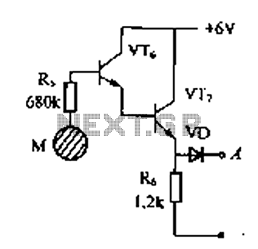
Delay electronic doorbell circuit - touch doorbell amplifier circuit The delay electronic doorbell circuit is designed to provide a user-friendly interface for doorbell activation, utilizing a touch-sensitive amplifier circuit. This circuit typically incorporates a touch sensor that detects user interaction,...
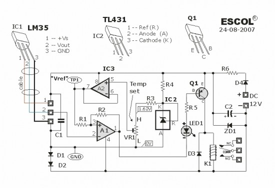
This temperature-controlled relay circuit is a simple yet highly accurate thermal control circuit that can be used in applications requiring automatic temperature regulation. The temperature-controlled relay circuit operates by monitoring the ambient temperature and activating or deactivating a connected load...
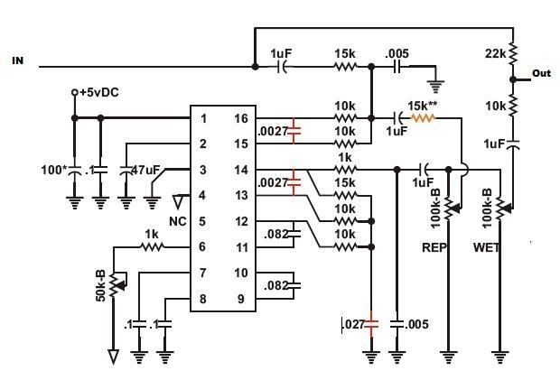
Recently, there has been a focus on Jeep repair due to an issue preventing the XJ from starting. However, during this time, progress has been made on initial modulation tests of the PT2399 circuit, resolving many bugs. The main...
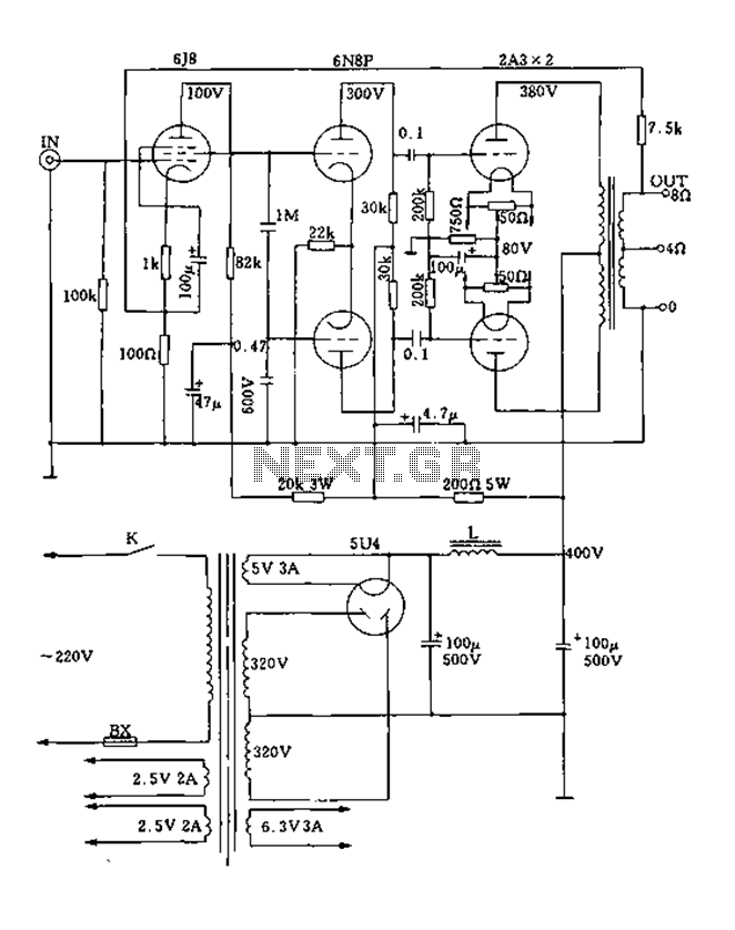
FIG. 2A3A is a low direct thermal resistance transistor with a resistance of only 800 ohms. The output transformer has a primary screen to load impedance of 3.5k ohms. The push-pull amplifier tube operates with a screen voltage ranging...
This is just one of the many bugging devices available on the eavesdropping market. The range includes pen and pencil holders, trophies, framed pictures, and office furniture with false bottom drawers. These products are readily sold to fledgling companies,...
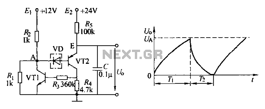
The application circuit depicted is a complementary sawtooth generator. In the schematic, VT1 is the transistor with a base current limiting resistor, which prevents excessive base current flow through the crystal tube. The resistor R4 acts as a bleeder...