
Computerize Your Room/House
The project involves constructing a computerized room automation system using an ISA prototyping board and various integrated circuits. The initial stage focuses on creating a Simple Parallel Port Interface, which serves as the foundation for the system. The choice of components, such as the 74LS series ICs, is critical for ensuring compatibility and functionality. The use of demultiplexers and address lines allows for scalability in controlling multiple outputs, making it suitable for various applications within a single room.
Soldering techniques and the layout of the prototyping board play a significant role in the project. The recommendation to use an experimenter's universal solder board is due to the complexity of connections required. Ensuring that connections are secure and correctly configured is paramount to avoid potential failures.
The integration of the printer port for both input and output operations highlights the versatility of this system. By utilizing existing programming languages such as BASIC or QBasic, users can easily send commands and receive data, facilitating interaction with the automated system.
Additionally, the project emphasizes the importance of thorough testing and validation of the circuit before deployment. This precaution is essential to prevent damage to both the circuit and the host computer, particularly when working with older hardware that may be more susceptible to errors.
Overall, this project represents a comprehensive approach to home automation, combining electronic design principles with practical programming techniques to create a functional and expandable system.So you`ve read about my Computerized Room or have seen those nifty home automation products advertised in the back of electronics magazines Or perhaps someone you know has done something similar. At any rate, you have decided to try it yourself. The first thing I will say, however is that it is not cheap. You will first need a computer, but since your reading this, I assume that you already have that taken care of. Second, you will have to buy about 20 IC`s and a very expensive ISA experimenters prototyping board. These boards cost anywhere from $16 to $45, and can be purchased from your local electronics store or from Jameco Electronics (See Where To Get Parts). They have a fairly wide selection. Buy the 8 bit version, the 16 bit varsion is not needed for this project. Since this is a major project, it will be presented in sections, starting with the Simple Parallel Port Interface.
The 8 Bit Output Card will come next, followed by the 8 Bit Input Card. All three interfaces came from the book "The Robot Builders Bonanza", by Gordan McComb. I must also stress that this is a major project and should not be attempted unlesss you have a good understanding of electronics. If done wrong, you run the risk of not only destroying the circuit, by also destroying an expensive computer as well.
Double, no, triple check your work to make absolutely sure that is free from errors before installing it in any computer. This is about the most basic interface you will see. It uses only 3 74376`s (74LS367). This interface provides 8 outputs (plus 3 address lines) and 5 inputs. This is usually enough for one room, providing you make use of some demultiplexers and the address lines.
You could have up to 128 output lines using the address lines, a 74LS138 and 8 74LS154`s. Begin construction by mounting the IC sockets on the board. I used a experimenters universal solder board due to the large number of wires that must cross. If a PC board were used, you would need either a multi-layer board or many, many jumpers. Now, solder wires along the top and bottom of the board, making all the connections between the IC sockets. Do not install the IC`s yet. Assemble the cable using 26 conductor ribbon cable and a 25 pin crimp connector. You will have one conductor left over so just "peel" it off. Connect the cable to the board and wire it into the circuit. I used an 18 pin socket to make connections to the outputs and inputs on the interface easy. You could do the same if you like, or use a terminal strip. You operate the interface by sending bit patterns to the printer port. BASIC, GWBASIC or QBasic are the languages of choice since most computers already have them installed (in yourDOSdirectory).
If you wish, you can download control software from my files section. Although designed primarily to get data out of the computer, the printer port has 5 input lines (on some computers it could be less). You access these lines with theINPfunction. This time, however, the decimal address is 889. The syntax of theINPcommand is: This is much more complicated then the parallel port interface, mostly because of the address lines used by the computer to send data to different devices plugged into it`s bus.
This interface is constructed on an IBM 8 bit prototyping board. These are available from Jameco Electronics (see Where To Get Parts). Connections are made with point to point soldering or wire wrap. Note that if you use the wire wrap method the board will require about 1/2 inch clearence on the connection side. Use sockets for all IC`s. Begin construction by first mounting the sockets. Depending on which board you buy, you might have lots or very little space. Connect the IC`s together using either point to point or wire wrap. I used a 36 pin connector to facilitate connection to the back of the computer, but you can use any other method.
Whatever the method, install that connector and wire it into the circuit now. You may now wire the connections to the bus (the gold contacts on the bottom of the card). If you need a reference as to what the bus connections are, check out The IBM Bus Pinout (I apologize for the poor image quality). It is a good idea to bypass power supply pins with. 1uf capacitors to avoid problems with interference, power supply spikes, etc. Triple check your work before installing the circuit in any computer. The simple circuit to connect the interface to relay`s is showen after the schematic. This input circuit can be built on the same board as the output circuit, and share the same bus connections.
This circuit is necessary if you wish to use almost any type of remote control circuit, which will most likely require more then 5 inputs as provided by the printer port. Since this is quite similar to the output circuit, I won`t go into the details again. Only the parts list and schematic will be showen, as well as the "power pins" chart. Controlling the cards is straight forward, using the basicINPandOUTstatements as explained in the Simple Parallel Port Interface.
The only difference is the address. The address for the input card is decimal 701 while the output card is decimal 703. This is the last section of this document. Choosing the right computer is getting harder these days. Since new computers no longer come with ISA slots, that basically means you are stuck using older machines. In a way this is good since it`s no great issue if you fry one. Pentium class machines are essentially junk these days and basically free. Pentium II and III machines are quickly dropping into that catagory. Just make sure that you triple check your work before installing it into any computer. Well, thats it. For more information on programming the parallel port, see Programming The Parallel Port In QBasic or Programming The Parallel Port In Visual Basic.
🔗 External reference
Related Circuits
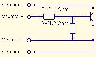
This is a straightforward guide to constructing a digital switch for a camera, enabling photo capture through microcontrollers. Required components include: 1. A digital switch for a camera can be implemented using a microcontroller, such as an Arduino or...
A cost-effective glove interface that achieves significant accuracy while enhancing comfort. The project involved acquiring several PowerGloves, extracting the flex sensors, and integrating them into sheaths on a lycra glove and suit. These sensors were connected to a multi-channel...
Measuring inductance is important for creating hand-made inductors, particularly when engaging in do-it-yourself (DIY) coil winding. An inductance meter adapter can facilitate this process. An inductance meter adapter is a vital tool for accurately measuring the inductance of coils and...

Creating a variable space in a small room can be enjoyable; however, designing an actuator to move a wall or room partition poses challenges. This can be achieved using an analog audio line delay. To implement a system that allows...
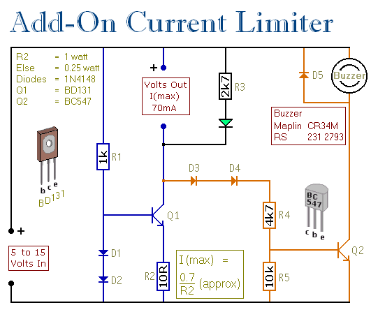
This circuit allows for setting a limit on the maximum output current from a power supply unit (PSU). It is particularly useful for initial project power-ups or during soak tests. By establishing an upper current limit, it protects both...
Logic-1 and logic-0 represent the states of digital signals, where logic-1 corresponds to a high voltage close to Vcc, and logic-0 corresponds to a voltage near neutral or ground. Logic-0 cannot be transformed into logic-1, while logic-1 can revert...