
Conducting pipe control rechargeable short delay circuit 2
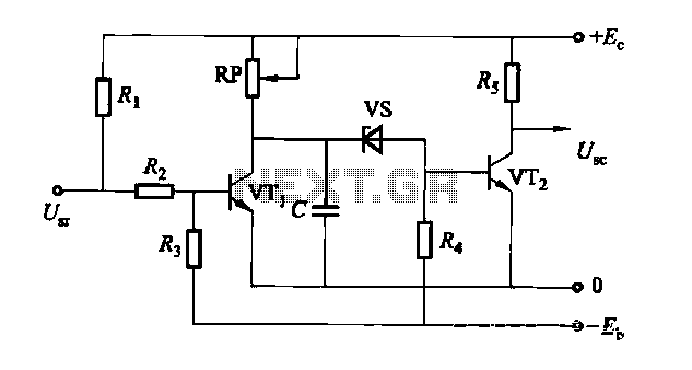
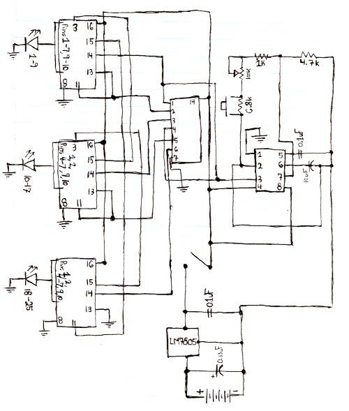
The rechargeable short delay circuit is designed for applications where a controlled delay is necessary before activating a connected load, such as a valve or actuator in a conducting pipe system. The core components of the circuit include a power supply, a timing mechanism, and two adjustment potentiometers (RP), which are crucial for customizing the delay duration.
The power supply can be a rechargeable battery or a DC power source, providing the necessary voltage and current for the circuit's operation. The timing mechanism typically consists of a resistor-capacitor (RC) network that determines the delay period. The two potentiometers allow for fine-tuning of both the resistance and capacitance values, enabling the user to adjust the timing characteristics according to specific application requirements.
When the circuit is activated, it begins charging the capacitor through the resistor. The time it takes for the capacitor to reach a certain voltage level, determined by the potentiometer settings, dictates when the output will trigger. This output can be connected to a relay, transistor, or any other switching device to control the load in the conducting pipe system.
The flexibility offered by the dual potentiometers enhances the circuit's versatility, making it suitable for a variety of applications requiring precise timing control. Proper implementation of this circuit can lead to improved efficiency and reliability in systems that rely on timed operations.Conducting pipe control rechargeable short delay circuit 2 Adjustment potentiometer RP, allows the delay time of several hundred milliseconds to several seconds.
Related Circuits
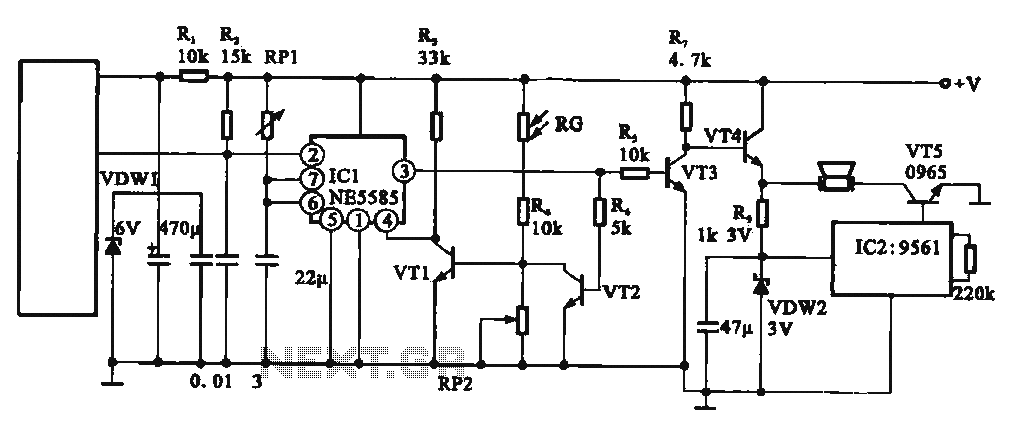
This circuit illustrates an automatic unattended burglar alarm system designed primarily for residential use, warehouses, and similar applications. The circuit features a pyroelectric infrared sensor integrated with a light control mechanism. It comprises components such as resistors (RG, RP2,...
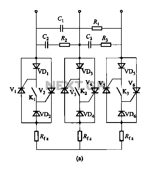
Figure 16-48 (a) illustrates the introduction of a six thyristor three-phase AC switching circuit, while Figure 16-48 (b) depicts the implementation of three triac circuits. These configurations are suitable for motors and other inductive loads. The six thyristor three-phase AC...
This analog switch circuit is designed to switch an analog line on or off. It consists of two analog switches in integrated circuit (IC) form that are controlled by two pushbuttons. The described analog switch circuit utilizes two integrated analog...
Here is the schematic for the circuit. Solder all the components onto a perfboard. The drawings may not be very clear. Essentially, the 555 timer generates a pulse. The circuit utilizes a 555 timer IC configured in astable mode, which...
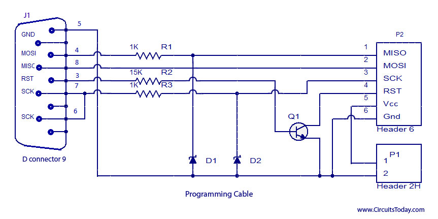
ISP programmer with circuit diagram for AVR Atmega32 microcontroller. This ISP burner circuit is an adaptation of the Pony programmer and uses PonyProg software. The ISP (In-System Programming) programmer designed for the AVR Atmega32 microcontroller allows for programming the microcontroller...
The circuit is designed to be powered directly by a power supply, which is why it does not include a transformer, rectifier, or filter capacitors in the schematic. However, these components can be added if desired. To operate the...
Warning: include(partials/cookie-banner.php): Failed to open stream: Permission denied in /var/www/html/nextgr/view-circuit.php on line 713
Warning: include(): Failed opening 'partials/cookie-banner.php' for inclusion (include_path='.:/usr/share/php') in /var/www/html/nextgr/view-circuit.php on line 713