
ISP Programmer for ATmega32 Microcontroller

The ISP (In-System Programming) programmer designed for the AVR Atmega32 microcontroller allows for programming the microcontroller directly on the circuit board. This method eliminates the need for external programming devices and simplifies the development and debugging process. The circuit diagram typically includes essential components such as a microcontroller, a crystal oscillator for clock generation, and a series of resistors and capacitors that ensure stable operation.
The Pony programmer adaptation integrates a USB interface, enabling communication between a PC and the microcontroller. The PonyProg software is utilized for programming and uploading firmware to the Atmega32. This software supports various programming modes and provides a user-friendly interface for developers.
Key components of the circuit include the Atmega32 microcontroller, a 16 MHz crystal oscillator for timing, and several passive components such as resistors and capacitors that filter and stabilize the power supply. The ISP header connects to the microcontroller's programming pins, allowing for direct access to the programming interface.
The circuit design emphasizes simplicity and efficiency, making it suitable for hobbyists and professionals alike. Proper layout and grounding techniques are crucial to minimize noise and ensure reliable programming. Overall, this ISP programmer circuit serves as a valuable tool for developing and testing applications based on the Atmega32 microcontroller.ISP programmer with circuit diagram for AVR Atmega32 micro controller.This ISP burner circuit is an adaptation of Pony programmer and uses ponyprog software 🔗 External reference
Related Circuits

PIC development/testing board. This is a PCB design for a basic PIC16F877 development board. All that is required is a 4 MHz crystal, two 22 pF capacitors, and one 4.7 kΩ resistor. The PIC16F877 development board is designed to facilitate...
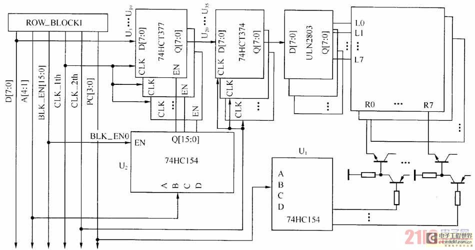
The large-scale LED display system utilizes a line-by-line scanning method and outlines the driving mechanisms to reduce hardware costs. It employs a 1/16 non-interlaced scanning mode, accommodating a total of 16 LED display panels. The schematic diagram of the...

This document discusses the use of small microcontrollers, such as those from the PIC and Atmel series, which typically operate at 5V and require less than 100mA for complete system functionality. Some PICs can function at lower voltages, such...
Atmel Flash devices are well-suited for development due to their ease and speed of reprogramming. They provide ample code space for applications, especially for projects involving the 89Cxx series with the C programming language. Atmel offers a wide selection...
This page presents a replacement circuit for the LM3909 LED Flasher/Oscillator utilizing discrete components. The circuit functions similarly to the integrated LM3909 but features minor variations in the component values used. Although the LM3909 is still available, it tends...
A slice of the SM2965 includes a canonical 80C32 microcontroller, FLASH memory, E2PROM (28SF512), SRAM for static data storage, and a watchdog timer (WDT). The cost performance of the SM2965 is notably high. This device is designed as a...