
Stepping HM4246 touch dimmer light circuit
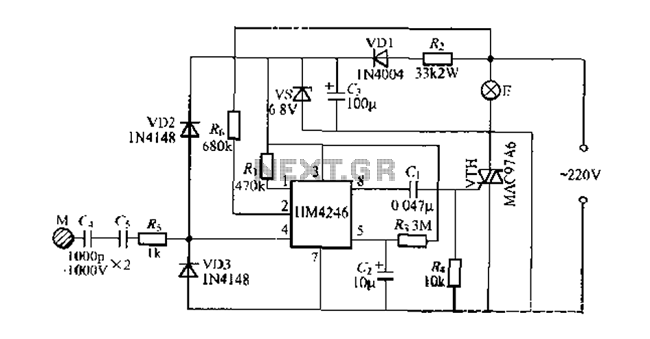
The touch dimmer integrated circuit, HM4246, is designed to provide a user-friendly interface for controlling the brightness of various lighting fixtures. Its four distinct lighting modes—dark, medium, light, and a touch-triggered function—allow for customizable illumination based on user preference. The design emphasizes low harmonic radiation emissions, making it suitable for sensitive environments.
The circuit's architecture is based on a standard DIP 8 package, which facilitates easy integration into various lighting systems. Each pin on the HM4246 serves a critical role in the operation of the dimmer. The clock signal input (Pin 1) synchronizes the circuit's timing, while the AC input frequency (Pin 2) ensures compatibility with standard electrical systems. The positive and negative power supply terminals (Pins 3 and 7) provide the necessary voltage for operation, typically in the range of 5 to 6V.
The touch-sensitive input (Pin 4) is a crucial feature that enables the user to adjust brightness levels with a simple touch. This is complemented by the sensitivity control terminal (Pin 5), allowing for fine-tuning of the touch response to accommodate different user preferences and environmental conditions. The null foot (Pin 6) is included for circuit stability and grounding purposes.
The pulse signal output (Pin 8) is designed to trigger a thyristor driver, allowing for efficient control of the connected lighting load. This feature is particularly beneficial for applications such as Feng spider lamps, where precise brightness control enhances the overall ambiance.
To ensure reliability and safety, the circuit design recommends the use of RJ-2W metal film resistors, which provide stable performance under varying conditions. Additionally, the use of CBB polypropylene capacitors rated for 1000V is critical to prevent voltage spikes that could harm the circuit or the user. Standard electrolytic capacitors, such as CD11-16V, can be employed for power smoothing.
In summary, the HM4246 touch dimmer integrated circuit is a versatile and reliable solution for modern lighting applications, combining ease of use with advanced features to meet diverse user needs.Development and production of special touch dimmer integrated circuit, it has a dark, medium, light, take along a touch against the four side light function for zero trigger, h armonic radiation emission is low. Has high touch sensitivity and stability, can be adapted to long cables and high sense of dummy load plate (-iOOpF), to be used for Feng spider lamp and other lighting with brightness adjustment night, which see Azerbaijan 1 circuit 34. HM4246 integrated circuit using standard DIP 8·?bullock, each pin functions can provide: O foot LK, a clock signal input terminal; feet Fl.
Is 60 2/50Hz AC input frequency; foot VT, -, is positive power supply terminal; feet TI. A touch-sensitive input; feet CI, as a sensitivity control terminal; foot N (1, null foot; V Zhi feet, the negative power supply terminal; feet AT, the pulse signal output, triggered thyristor drive canthus .HM4246 power supply voltage in the range of 5 ~ 6 SV. the H, R. require the use of RJ-2W metal film resistors, e, c5 should withstand loooV the CBB polypropylene capacitors to ensure the safety of users.
[1 :,. G available CD11-16V ordinary electrolytic capacitors use, when the hand touched repeatedly M, bulbs E state order: dark towel Koichi Koichi -J brightest lights of a dark Koichi. cycling for selection.
Related Circuits
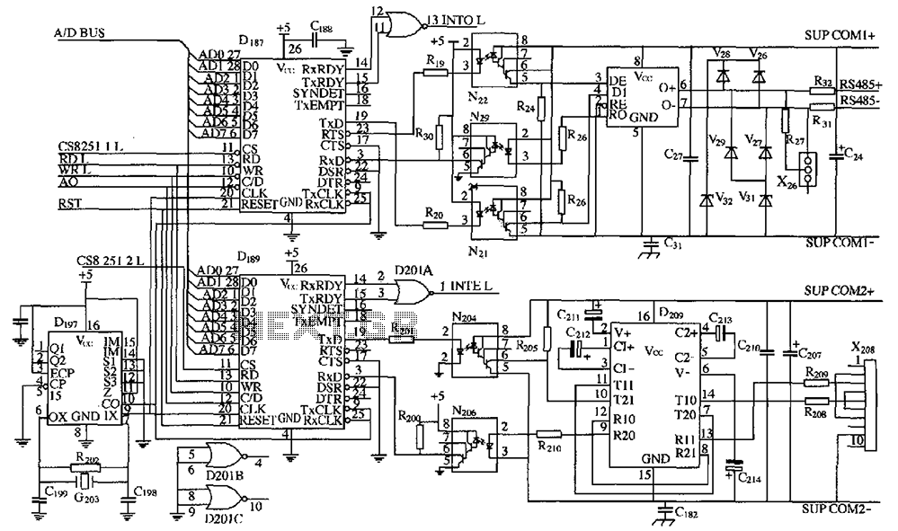
As shown in the figure, D187 is a universal asynchronous receiver-transmitter (UART). Its RX/TX signals are received through optocouplers N21, N22, and N29, facilitating RS-485 communication. The interface receiver/transmitter D28 and microprocessor D211 are completely optically isolated. D197 serves...
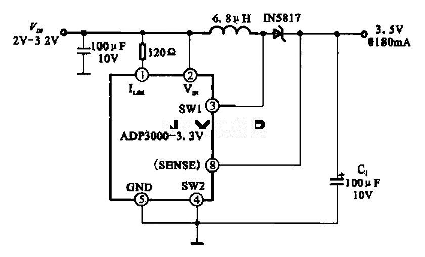
Boost 3.5V regulator circuit. This chip can boost or create a stable voltage supply from approximately 3V DC to a DC voltage of 3.5V. The boost regulator circuit is designed to increase a lower DC voltage, specifically from around 3V...
The circuit utilizes a 555 timer configured as a multivibrator, where the oscillation frequency is determined by resistors R1, R2, and capacitor C1. The frequency formula is given by fo = 1.443 / ((R1 + R2) * C1). The...
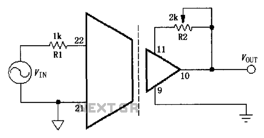
The gain adjustment circuit for the ISO103 is illustrated. The circuit features a gain trimming potentiometer, R2, which serves to enhance the gain accuracy and offset of the ISO103, thereby allowing for external adjustments. R2 provides a gain trim...
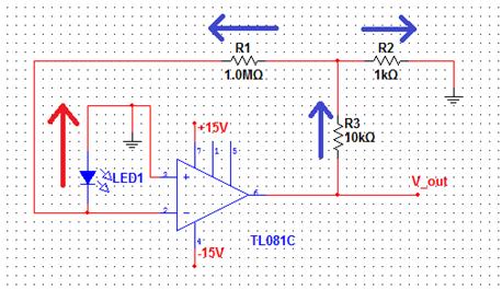
The comparator output drives an LED, and the next step is to sense the intensity of the LED. This lab involves building a light detector circuit using an operational amplifier (op-amp) and a standard light-emitting diode (LED). It is...
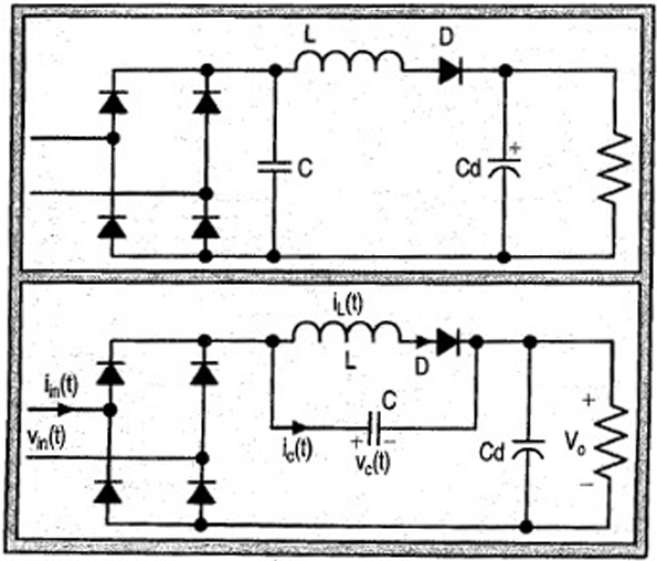
The input current for a passive power factor correction (PFC) circuit is not affected by variations in the output ripple, resulting in the need for a smaller inductance compared to earlier circuit designs. Passive power factor correction circuits are utilized...