
Constant Current Battery Charger circuit

The circuit described involves using a higher voltage battery to charge a lower voltage battery through a series resistor. The primary function of this resistor is to limit the current flowing into the lower voltage battery, ensuring safe and effective charging. The resistor value can be calculated using Ohm's Law, specifically by applying the formula:
\[ R = \frac{V_{diff}}{I_{charge}} \]
where \( R \) is the resistance in ohms, \( V_{diff} \) is the voltage difference between the two batteries, and \( I_{charge} \) is the desired charging current in amperes.
For example, if the higher voltage battery is 12V and the lower voltage battery is 6V, the voltage difference \( V_{diff} \) is 6V. If the desired charging current is 0.5A, then the required resistor value can be calculated as follows:
\[ R = \frac{6V}{0.5A} = 12 \, \Omega \]
In practice, the resistor must be rated for the power it will dissipate, which can be calculated using the formula:
\[ P = I^2 \times R \]
In this case, substituting the values gives:
\[ P = (0.5A)^2 \times 12 \, \Omega = 3 \, W \]
Thus, a resistor rated for at least 3W should be used to ensure safe operation without overheating.
This simple circuit is effective for charging smaller batteries in applications where a higher voltage source is readily available. However, it is crucial to monitor the charging process to prevent overcharging, which can damage the battery. Additional components such as a diode may be included to prevent reverse current flow once the charging source is removed, thereby protecting both batteries.A simple method of charging a battery from a higher voltage battery is shown in the circuit below to the left. Only one resistor is needed to set the desired charging current and is calculated by dividing the difference in battery voltages by the charge current..
🔗 External reference
Related Circuits
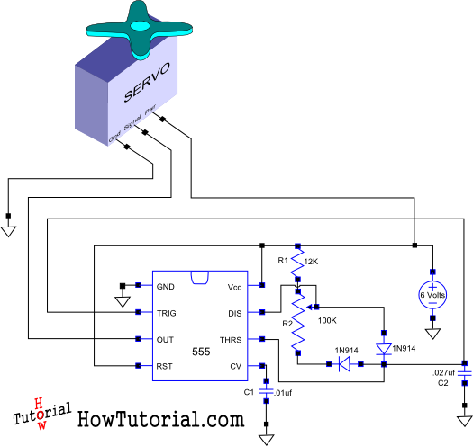
This document outlines the design of a simple circuit that enables control of a servo motor and allows for testing its functionality. The circuit for controlling a servo motor typically consists of a microcontroller, a power supply, and the servo...
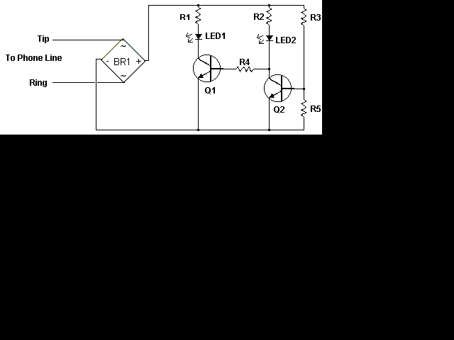
This circuit addresses the issue of phone line interruptions caused by simultaneous use of a modem or fax machine when another phone is picked up. It indicates the status of the phone line by illuminating a red LED when...
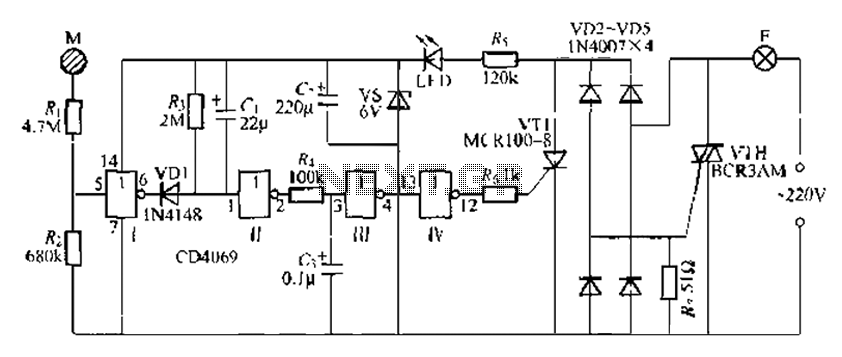
The CD4069 is a digital integrated circuit that utilizes boron to delay the activation of a light touch. It employs a j-wire connection force method and can directly replace a standard light switch without requiring changes to the existing...
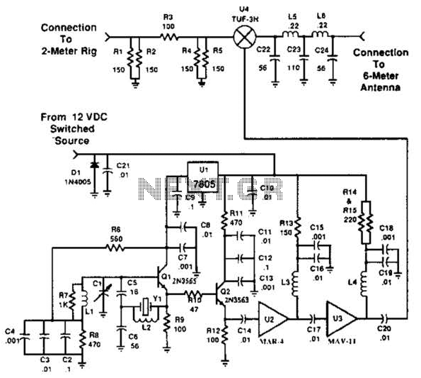
This transverter utilizes the bilateral properties of a balanced mixer to generate a 6-meter output from 2-meter inputs. The component Y1 is a 90-MHz crystal. It is important to note that the input frequency on the 2-meter band is...
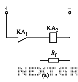
The circuit depicted in Figure 6-24 includes a relay coil with both ends connected in parallel to either a resistor Rf or an auxiliary diode VD. This configuration is equivalent to providing power after a short circuit, which increases...
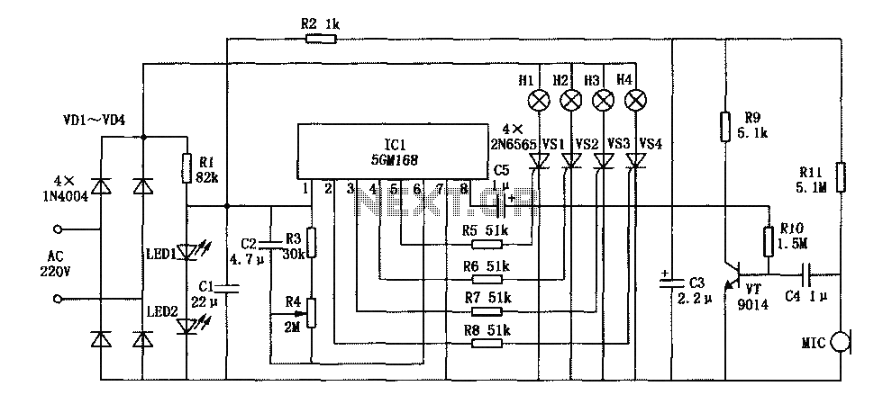
This document describes a family karaoke lighting design that employs various methods to control the circuit. The control circuit presented here features a four-way light output with loop jumping and speed control capabilities. The practical circuit utilizes a microphone...