
how do you build a simple circuit to control a servo
The circuit for controlling a servo motor typically consists of a microcontroller, a power supply, and the servo motor itself. The microcontroller serves as the brain of the circuit, providing the necessary signals to the servo for position control. Commonly used microcontrollers for such applications include Arduino, Raspberry Pi, or any suitable embedded system that can output PWM (Pulse Width Modulation) signals.
The power supply must be capable of delivering the required voltage and current for the servo motor, which is generally in the range of 4.8V to 6V for standard servos. It is essential to ensure that the power source can handle the stall current of the servo, which can be significantly higher than the operating current.
The servo motor is connected to the microcontroller via a PWM signal pin. The microcontroller generates a PWM signal that varies in width, which corresponds to the angle of the servo arm. A typical PWM signal for servo control has a frequency of around 50 Hz, with pulse widths ranging from 1 ms (0 degrees) to 2 ms (180 degrees).
Additional components may include resistors for signal conditioning, capacitors for noise filtering, and possibly a transistor or relay if higher current handling is necessary for the servo operation. Proper grounding and decoupling techniques are crucial to ensure stable operation and to prevent any interference that could affect the servo's performance.
The layout of the circuit should be designed to minimize noise and ensure that the power supply lines are adequately decoupled from the signal lines. It is advisable to use a breadboard for initial testing before finalizing the design on a printed circuit board (PCB) for durability and reliability in practical applications.
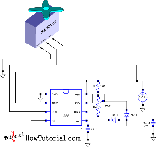
In summary, the design of a simple servo control circuit involves careful selection of components, proper signal generation through PWM, and attention to power supply requirements to achieve effective control of the servo motor.This is how I designed a simple circuit that allows you to control a servo and put it through its paces.. 🔗 External reference
Related Circuits
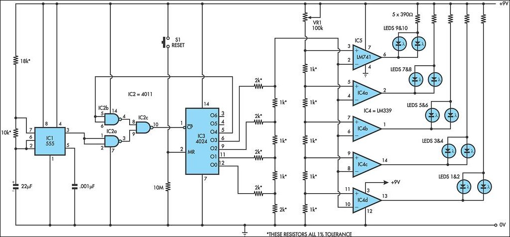
This LED circuit replicates the initial LED sequence currently utilized by FISA for Formula One racing. It can also be employed with slot car sets, such as HO scale AFX, Life Like, or Tyco sets, or used in communication-controlled...
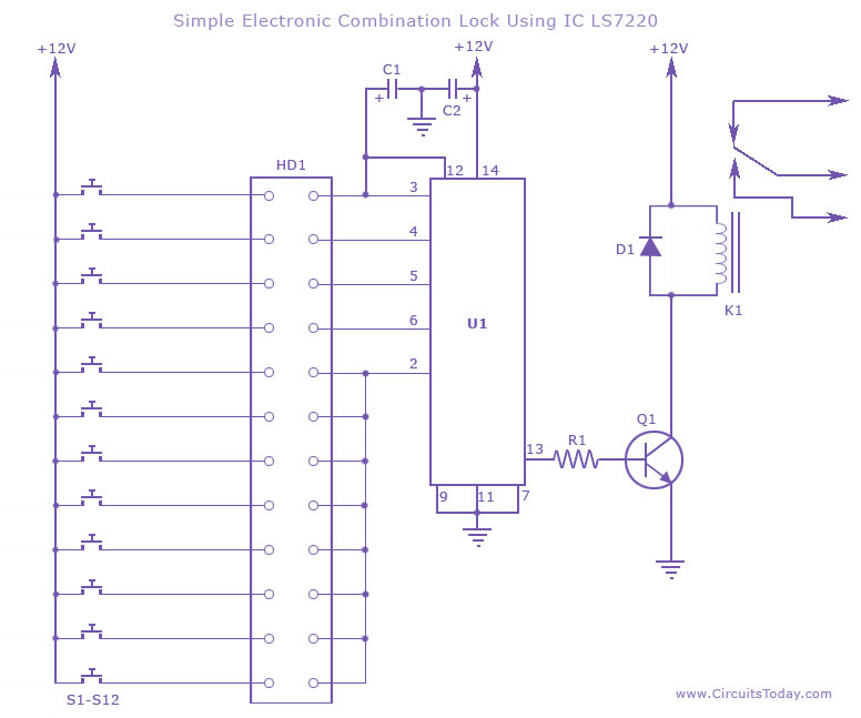
This circuit diagram illustrates a simple electronic combination lock utilizing the IC LS7220. It is designed to activate a relay for controlling any device (on & off) when a specific combination of four digits is entered. The circuit operates...
This circuit is not a novelty, but it proved so useful, simple and cheap that it is worth building. When the positive (Red) probe is connected to a DC positive voltage and the Black probe to the negative, the...
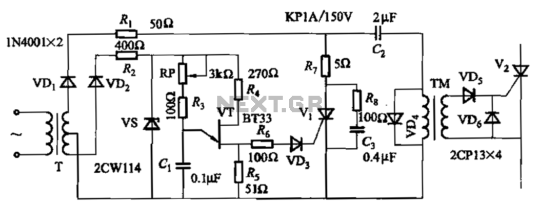
The adjustment potentiometer RP allows for modification of the pulse phase shift range, which spans from 0 to -1600, providing higher sensitivity. The circuit incorporating the adjustment potentiometer RP is designed to facilitate precise control over the phase shift of...
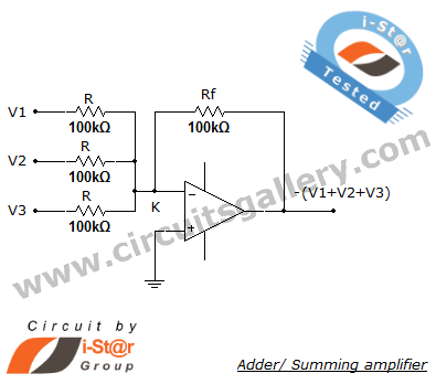
A summing amplifier, also known as an adder, is utilized to combine two or more signal voltages. This voltage adder circuit is straightforward and allows for the addition of multiple signals. It has a wide range of applications in...
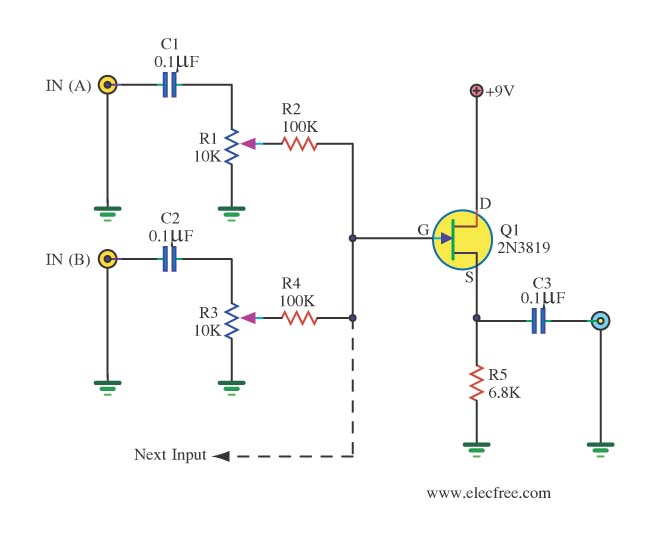
The audio from each radio will be connected to the iPod audio output and vice versa. This setup alters the impedance and can affect sound levels, potentially damaging the audio circuits of one or more radios involved. It is...