
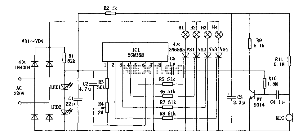
Family Kara OK lights 5GM168 a control circuit diagram
The family karaoke lighting design integrates an innovative control mechanism that enhances the user experience by synchronizing light patterns with audio input. The circuit architecture includes three primary components: a power supply circuit, a control circuit, and an audio amplifier, each playing a crucial role in the overall functionality.
The power supply circuit is responsible for providing the necessary voltage and current to the entire system, ensuring stable operation. It typically consists of a transformer, rectifier, and filter capacitors to convert AC voltage from the mains supply to the required DC voltage for the control circuit and audio amplifier.
The control circuit is the core of the lighting system, utilizing a microcontroller or a combination of logic gates to process the audio signals captured by the microphone. The circuit is designed to interpret the amplitude of the incoming sound waves, allowing it to modulate the speed and pattern of the light outputs. The four-way light output can be achieved using an array of LEDs or light bulbs, each connected to a relay or transistor switch that is controlled by the microcontroller. The loop jumping feature allows for dynamic transitions between different light patterns, enhancing the visual effects in synchronization with the music.
The audio amplifier serves to boost the signal received from the microphone, ensuring that even quieter sounds can be detected and processed by the control circuit. This component typically includes operational amplifiers configured in a non-inverting mode to provide gain, along with filtering stages to eliminate noise and enhance the clarity of the audio signal.
In summary, this karaoke lighting control circuit is a sophisticated system that combines audio detection with responsive lighting effects. It provides an engaging environment for home entertainment by allowing users to experience a vibrant light show that reacts in real-time to the music being played.Family karaoke 0K lighting design of a variety of methods to control circuit, the control circuit described here is a kind of four-way light output, loop jump, speed controllab le practical circuit. Microphone to pick up speed to jump the lights with acoustic signal strength varies, acoustic signal stronger, faster jump lights, whereas the slower speed. home lighting control circuit is shown. The circuit consists of a power supply circuit, a control circuit and audio amplifier.
Related Circuits
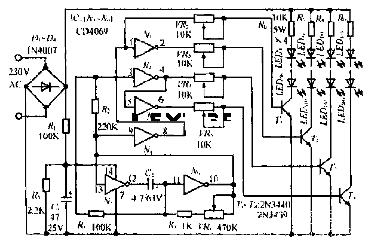
An air bridge after the bullock Phi Beach in Sichuan utilizes direct beam lights. Control is implemented for six buildings with filtered output at specific voltage levels. The system includes a small 4H servant for pressure control, and components...
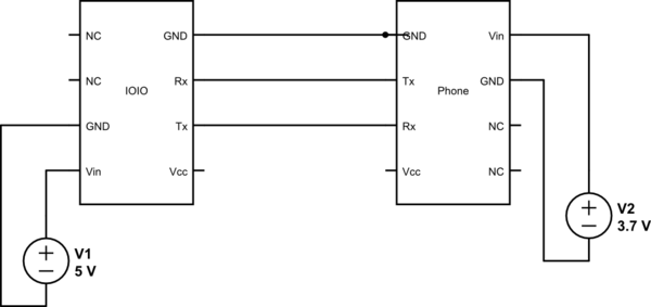
This project utilizes Sparkfun's IOIO for Android, focusing on power consumption concerns. The IOIO board can provide the phone with 500 mA charging, which may be excessive for continuous operation. The proposed solution is to power both the phone...
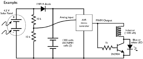
This example demonstrates the PWM (pulse-width modulation) output of a microcontroller controlling a Joule Thief style voltage booster to power a white LED. The circuit described utilizes a microcontroller to generate a PWM signal, which is an effective method for...
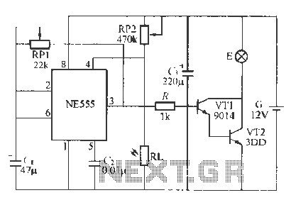
This circuit utilizes battery-powered blinking warning lights for roadblocks. It can operate on AC power to create barricades with warning indicators. The circuit incorporates an NE555 timer and resistors RP1 and RP2, along with resistor R1, to form a...
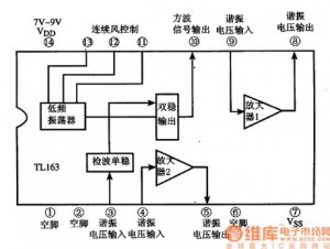
The following circuit illustrates the TL163 integrated circuit (IC) used in an ultrasonic remote control circuit diagram. Features include a detector, high-gain amplifier, and low-frequency response. The TL163 IC is designed to facilitate ultrasonic signal processing, making it suitable for...
This is a portable, high-power incandescent electric lamp flasher. It functions as a dual flasher (alternating blinker) capable of managing two independent 230V AC loads (bulbs L1 and L2). The circuit is entirely transistorized and operates on battery power....