
Constant current motor drive circuit

This circuit is designed to provide a reliable method for driving DC motors while minimizing the risk of damage due to stalling or lock-up conditions. The core functionality relies on a feedback mechanism that monitors the motor's current draw. When the motor stalls, the circuit automatically adjusts the current to a predetermined safe level, preventing overheating and potential damage to the motor and associated components.
The essential components of this circuit typically include a DC motor, a current sensing resistor, an operational amplifier (op-amp) configured as a comparator, and a power transistor or MOSFET for driving the motor. The current sensing resistor is placed in series with the motor to measure the current flowing through it. The voltage across this resistor is fed into the op-amp, which compares it against a reference voltage that corresponds to the maximum allowable current.
In normal operation, when the motor runs without stalling, the current remains below the threshold set by the reference voltage. However, if the motor begins to stall, the current will increase, causing the voltage across the sensing resistor to exceed the reference level. The op-amp will then output a signal that turns off or reduces the drive to the power transistor, effectively limiting the current supplied to the motor.
This approach ensures that the motor can be operated safely under various load conditions without the risk of thermal damage. Additionally, the circuit can be designed to include features such as hysteresis to prevent rapid cycling of the motor drive during minor fluctuations in load, further enhancing reliability.
Overall, this minimum device circuit provides a robust solution for driving DC motors in applications where stalling is a concern, ensuring longevity and operational safety.This minimum de vice circuit can be used to drive dc motors where there is some likelihood of stalling or lock up if the motor locks, the current drive remains constant and the system does not destroy itself.
Related Circuits

The operation of the rain alarm circuit is explained in detail. The rain alarm project is outlined along with a circuit diagram. The rain alarm circuit is designed to detect the presence of rain and alert users through an audible...
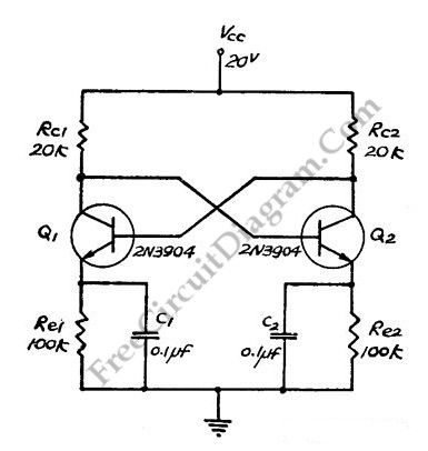
This flip-flop circuit functions as a free-running astable multivibrator, where the bases and collectors of both emitter-biased transistors are directly coupled. The switching action is facilitated by a capacitor in each emitter circuit, resulting in the generation of triangle...

The circuit primarily consists of the NAND gate IC1 (CD4096), a counting/timing distribution circuit IC2 (CD4017), an analog electronic switch IC3 (CD4066), and a D flip-flop IC4 (CD40174), along with other components. The controller is capable of managing the...
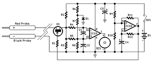
Short circuits or broken PCB tracks can be easily identified using a multimeter; however, this tool may yield inaccurate results when testing the efficiency of a transistor or diode unless the component is unsoldered and removed from the PCB....

This is a straightforward and easy-to-assemble multi-purpose alarm system. It can be constructed using stripboard or veroboard along with a few inexpensive, readily available components. The alarm is designed to be installed on doors, windows, sheds, garages, cupboards, and...
The refrigerator turned on, causing the lights to brighten. Initially, it seemed like an illusion, but after observing multiple cycles, the phenomenon persisted. When the microwave was activated, the lights dimmed. The refrigerator's operation appeared to influence the brightness...