
Three of the five band equalizer circuit transistor
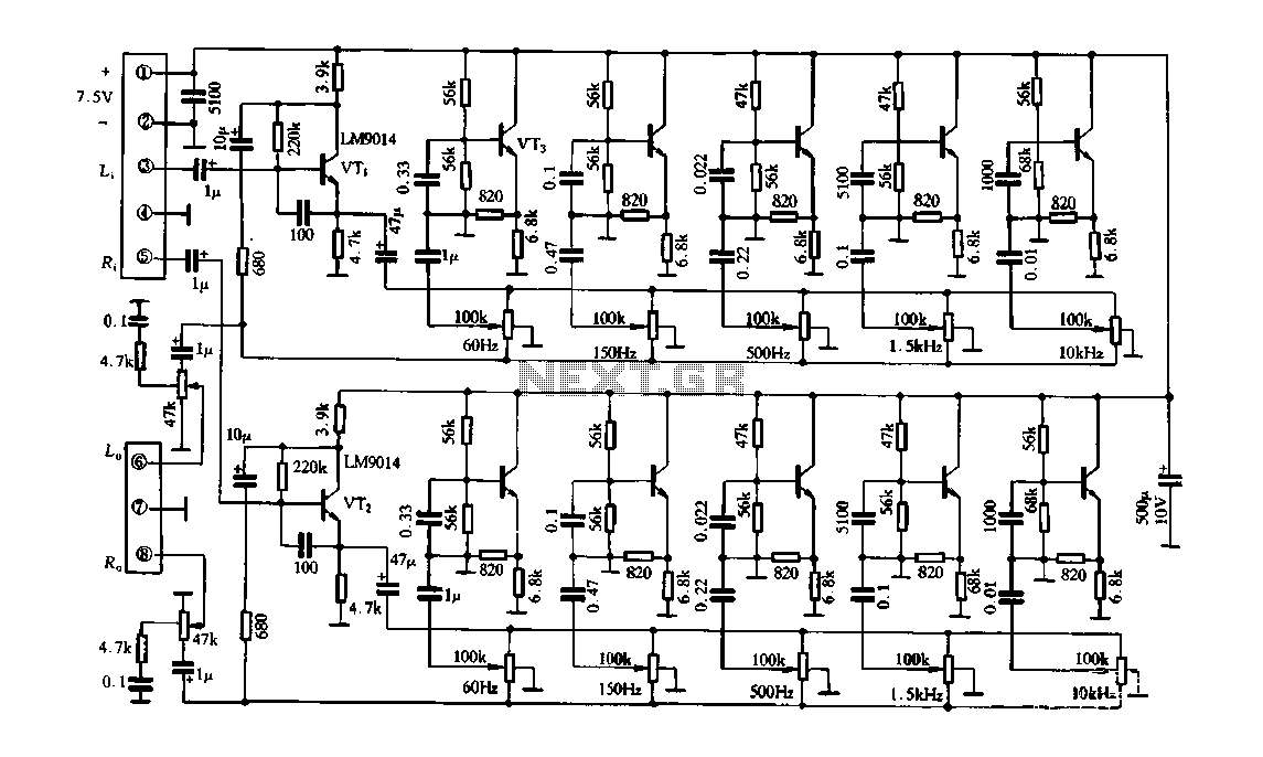
The circuit depicted in Figure 4-33 employs a common amplifier configuration, which is a foundational element in analog electronics. The common amplifier is characterized by its ability to provide significant voltage gain while maintaining stability within the circuit. The inclusion of analog inductive circuits allows for the manipulation of inductive components, which can be essential for various applications such as filtering or signal processing.
In this configuration, the transistor plays a crucial role in the analog inductive circuit. By increasing the bias resistor, the operating point of the transistor is adjusted, leading to improved thermal stability and performance. This adjustment is critical in ensuring that the amplifier operates within its optimal range, minimizing distortion and enhancing linearity.
The feedback loop of the amplifier is an integral part of its design, as it dictates the gain and stability of the overall system. The potentiometer connected to this feedback loop allows for fine-tuning of the circuit's response. By adjusting the potentiometer, the feedback can be modified, which influences the gain and bandwidth of the amplifier. The center tap of the potentiometer being grounded is a common practice, as it provides a reference point for the feedback voltage, ensuring consistent performance across varying conditions.
Overall, this circuit configuration exemplifies the interplay between biasing, feedback, and stability in amplifier design, making it suitable for a wide range of applications in electronic systems.Figure 4-33 and using substantially the same circuit configuration, the common amplifier and analog inductive circuits are provided, but its analog inductive circuit transistor increases a bias resistor, the circuit more stable. Adjusting potentiometer connected to the feedback loop of the amplifier, the center tap to ground.
Related Circuits
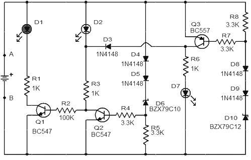
When the battery voltage is 11.5V or less, transistor Q1 is activated, and LED D1 will illuminate. When the battery voltage is between 11.5V and 13.5V, transistor Q2 is activated, causing LED D2 to light up. At a battery...
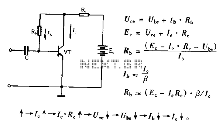
Bias voltage negative feedback circuit The bias voltage negative feedback circuit is a crucial component in various electronic applications, particularly in amplifiers and oscillators. This circuit is designed to stabilize the operating point of a transistor or operational amplifier by...
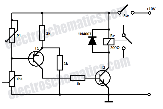
Safety is a significant concern in many motor-driven applications. This is particularly true in industrial settings where motion begins immediately upon the application of power. In motor-driven applications, safety mechanisms are essential to prevent accidents and ensure the well-being of...
This compact circuit is designed to be cost-effective, particularly useful during instances when the power supply is interrupted, such as while taking a shower. The backup lamp remains off as long as the CdS photocell is exposed to light...
The SC41343 is designed as a type of infrared, ultrasonic, or RF remote control launch coding circuit. The internal circuit comprises a sequence generator, control logic circuit, 4-bit shift register, data extraction circuit, and latch circuit. Features include the...
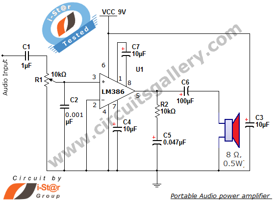
The i-St@r presents a simple mini audio amplifier circuit schematic utilizing the LM386 low voltage audio power amplifier IC. This circuit is designed to power medium-sized speakers from a music player that typically drives only earphones (LM386 headphone). The...