
Constant Temperature Circuit
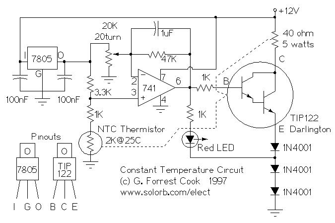
The constant temperature circuit described is designed to maintain a stable temperature in various applications, utilizing low power consumption to enhance efficiency. The primary components of this circuit typically include a temperature sensor, such as a thermistor or thermocouple, an operational amplifier (op-amp), and a control element like a relay or a transistor to regulate heating or cooling devices.
In operation, the temperature sensor continuously monitors the ambient temperature and sends a voltage signal to the op-amp. The op-amp compares this signal against a predefined reference voltage that corresponds to the desired setpoint temperature. When the sensed temperature deviates from the setpoint, the op-amp's output changes, triggering the control element to activate or deactivate the heating or cooling mechanism.
To improve stability and response time, feedback mechanisms can be incorporated, allowing for adjustments based on the rate of temperature change. Additionally, hysteresis may be applied to prevent rapid switching of the control element, which can lead to wear and tear or inefficiencies.
The circuit can be tailored for specific applications by selecting appropriate components and tuning parameters such as gain, setpoint, and response time. This versatility makes it suitable for use in various fields, including HVAC systems, laboratory equipment, and industrial processes where precise temperature control is essential.Constant Temperature Circuit. (C) G. Forrest Cook 1997 Introduction This circuit is a generic low power temperature controller that can be used for stabilizing temperature. 🔗 External reference
Related Circuits
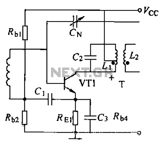
A common intermediate frequency amplifier circuit is presented, along with its components and parameters. The reference values for the components are as follows: 1) Transistors: VT1 to 3DG19, Vcc = 6V. 2) Resistance values: R1 = 50 kΩ, R2...
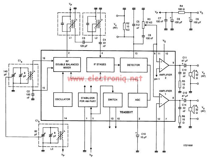
The TEA5551T monolithic integrated radio circuit can be utilized to design an AM radio receiver, intended for use as a portable radio receiver with headphones. The TEA5551T radio receiver circuit encompasses all necessary components for a complete AM receiver,...
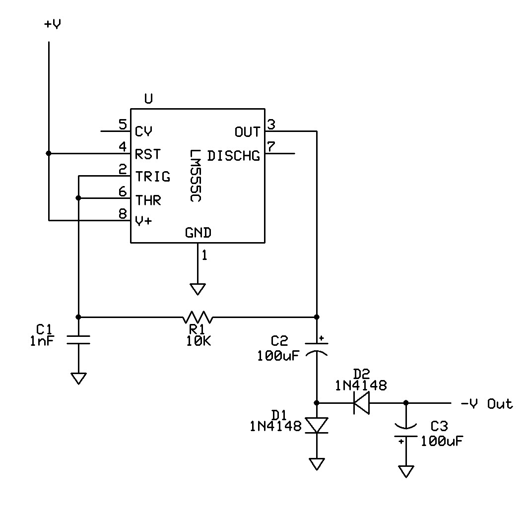
Can a 555 negative supply circuit, like the one below I pulled from another schematic, supply enough negative voltage to an LM324 and an AD736JN? The 555 timer integrated circuit can be configured to generate a negative voltage supply,...
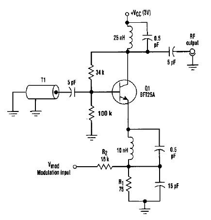
This varactorless high-frequency modulator electronic project must be powered by a simple DC 3-volt power source, such as a 3-volt battery. Traditionally, high-frequency oscillators are frequency-modulated using a varactor. However, varactors typically require a significant voltage change to achieve...
A simple battery charging circuit is designed using a flyback converter current-limited power supply to charge lead-acid batteries. This circuit is developed by Maxim Integrated. The described battery charging circuit utilizes a flyback converter topology, which is well-suited for applications...
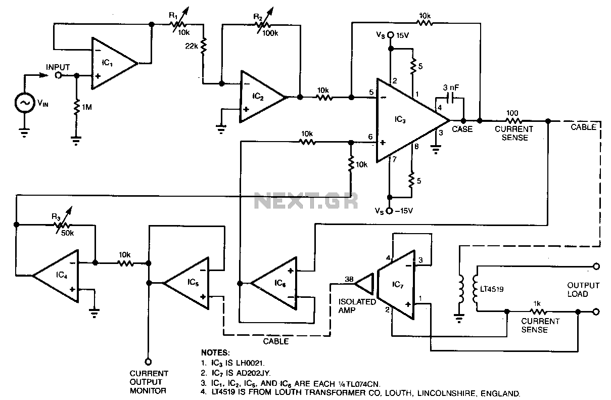
Most circuits that provide an electrical stimulus for research subjects are constant-voltage designs; this circuit is a constant-current design. Stimulator circuits must be isolated for two reasons: to ensure safety and to minimize interference. Isolated stimulators are essentially two-terminal...
Warning: include(partials/cookie-banner.php): Failed to open stream: Permission denied in /var/www/html/nextgr/view-circuit.php on line 713
Warning: include(): Failed opening 'partials/cookie-banner.php' for inclusion (include_path='.:/usr/share/php') in /var/www/html/nextgr/view-circuit.php on line 713