
256 Run Light (8bit Bin Up-Down)

The circuit utilizes an 8-bit up/down counter, which is capable of counting both upwards and downwards based on the control signals provided. The primary function of the counter is to maintain a count that can be displayed or utilized for various applications, such as timing or sequencing in digital systems. The counter receives input signals that dictate whether it should increment or decrement its count.
Complementing the counter is an 8-bit binary to 256 decimal decoder. This decoder takes the binary output from the counter and converts it into a one-hot encoded signal that represents one of the 256 possible states. Each output of the decoder corresponds to a unique count value from the counter, allowing for straightforward interpretation of the counter's state.
The integration of these two components results in a run light system, where the current count can be visually represented through LEDs or other indicators. As the counter increments or decrements, the corresponding output from the decoder activates the appropriate light, providing a clear visual indication of the current count status.
In practical applications, this circuit can be employed in various digital devices requiring counting functions, such as timers, event counters, or even in gaming systems where score tracking is essential. The design is efficient, leveraging the simplicity of binary counting with the versatility of a decoder to provide a user-friendly output. Proper power supply considerations and signal integrity must be maintained to ensure reliable operation of the counter and decoder in the intended application.This is A 8 bit Up/Down Counter that together with the “8 Bit Binary to 256 Decimal (1 of 256) Decoder “ makes a Run Light. I tried to to put all the 256.. 🔗 External reference
Related Circuits
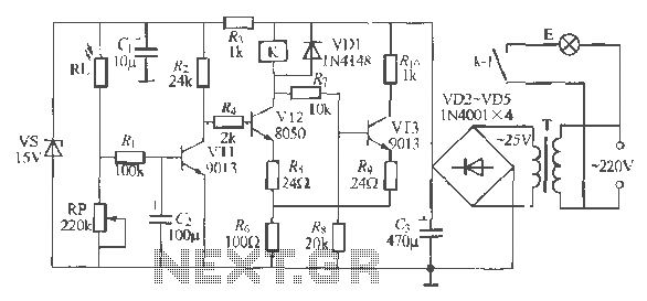
The circuit operates as a light-activated switch that controls white moving lights. It features high sensitivity, stable performance, and good anti-interference characteristics. A photosensitive resistor (RI) is employed to detect ambient light levels. During the day, the resistor exhibits...

This circuit differs from the standard 555 oscillator circuit by placing the LED in the capacitor reset line (pin 7). This configuration reduces overall current and prevents high peak LED current from draining the battery. The forward voltage drop...
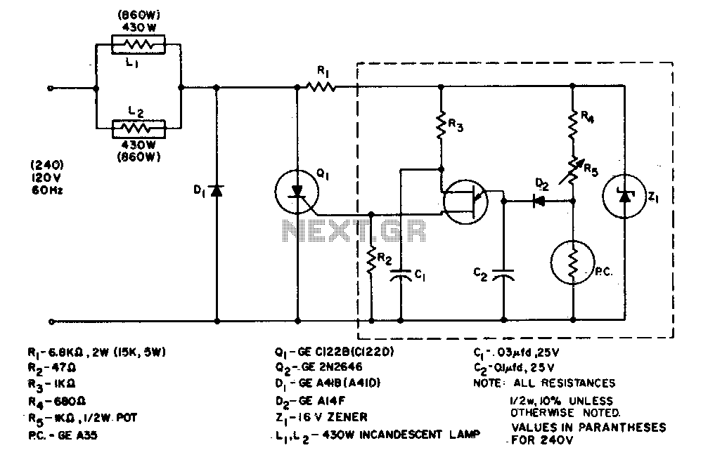
The system is designed to regulate an 860-watt lamp load from half to full power. This is achieved through the controlled half-plus-fixed half-wave phase control method. Applying half power to an incandescent lamp results in 30% of the full...
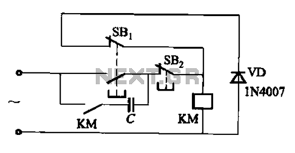
An AC contactor switch, when used with DC or pulse DC excitation, can minimize short circuit and core power consumption. This results in a significant reduction in the power consumption of the electromagnet, which can eliminate noise and reduce...
Electronics tutorial on combinational logic circuits that utilize logic gates to create multiplexers, encoders, and solid-state switches. Combinational logic circuits are fundamental components in digital electronics, characterized by their ability to produce outputs based solely on the current inputs, without...
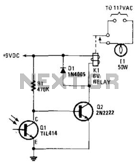
A phototransistor detects daylight. At dusk, it stops conducting, and Rl biases Q2, activating Kl, which turns on the light. At dawn, Ql begins to conduct, cutting off Q2. Kl deactivates, and the light turns off. The circuit utilizes a...