
Continuity tester for pcb
With a 1.5-volt power supply, the voltage is inadequate to turn on any semiconductor connected to the test terminals. A telephone earpiece can be used, although a 30-ohm speaker would also function effectively.
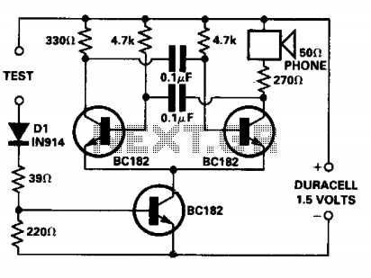
The continuity tester circuit employs a multivibrator configuration, which is advantageous for generating square wave outputs. This is achieved through the interaction of transistors T1 and T2, which toggle their states based on the input from T3. When the test leads are shorted, the circuit experiences a change in the input conditions, causing T3 to conduct and subsequently switch on T1 and T2, resulting in an audible or visual indication of continuity.
The components associated with T3 play a vital role in determining the sensitivity and operational threshold of the tester. D1 is utilized for biasing and ensuring that the input to T3 remains stable under varying conditions. Resistors R1 and R2 set the appropriate gain and enable the circuit to function effectively without drawing excessive power. The test resistance serves as the variable element, allowing the user to determine if the circuit under test is complete or if there is a fault.
In practical applications, the choice of a telephone earpiece or a 30-ohm speaker as an output device provides flexibility. The low supply voltage of 1.5 volts ensures that the tester remains safe for use on sensitive electronic components, preventing damage while still providing reliable continuity testing. The design's simplicity and efficiency make it an essential tool for electronics engineers and hobbyists working with printed circuit boards.The continuity tester is for tracing wiring on printed circuit boards. It only consumes any appreciable power when the test leads are shorted, so no On/Off switch is used or required. The applied voltage at the test terminals is insufficient to turn on diodes or other semiconductors. Resistors below 50 ohms act as short circuit; above 100 ohms as open circuit. The circuit is a simple multivibrator—Tl and T2, which are switched on by transistor T3. The components in the base of T3 are Dl, Rl, R2, and the test resistance. With a 1.5 volt supply, there is insufficient voltage to turn on a semiconductor connected to the test terminals. The phone is a telephone earpiece but a 30 ohm speaker would work equally as well. 🔗 External reference
Related Circuits

Car and Motorcycle Battery Tester Circuit. Going camping today often requires bringing various electronic devices for daily activities or entertainment. Typically, a charged lead-acid battery and a power source are essential. The Car and Motorcycle Battery Tester Circuit is designed...
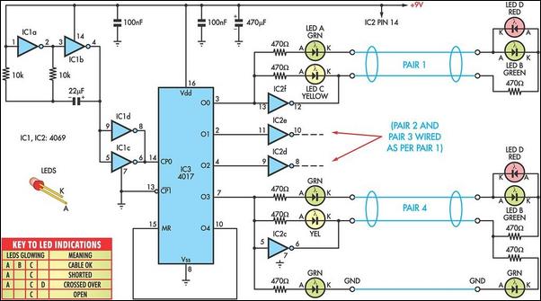
You do not need access to advanced testing equipment to check and troubleshoot computer data cables. Instead, this simple device will provide a quick indication of the status. This device functions as a basic cable tester, designed to assess the...
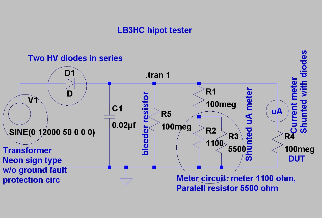
The design is based on concepts from K8CU and AG6K, but the circuit has been simplified and uses different components. The mechanical encapsulation has also been modified. LTspice was utilized to verify the tester prior to construction. The schematic...

The circuit does not guarantee the testing of all defective MOSFETs or all fault conditions in MOSFETs. If the MOSFET is functional, it will operate within the astable multivibrator circuit, resulting in the LED flashing. The described circuit employs an...
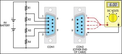
Many cable testers have been previously published, some of which are quite complex. However, here is a cost-effective and straightforward alternative. It utilizes only a 9V battery, two mating connectors, and several resistors, along with a multimeter for voltage...
Inspect the work for potential dry joints, shorts across adjacent tracks, or soldering flux residues, as these often lead to issues. Recheck all external connections to and from the circuit for any mistakes. Ensure that all polarized components are...