
Mosfet TESTER

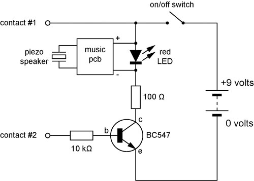
The described circuit employs an astable multivibrator configuration, which is a type of oscillator that continuously switches between its high and low states, producing a square wave output. In this setup, the MOSFET acts as a switching element that controls the operation of the LED. When the MOSFET is functioning correctly, it allows current to flow through the LED, causing it to flash at a frequency determined by the timing components of the multivibrator.
The astable multivibrator circuit typically consists of a pair of resistors and a capacitor connected to a voltage source and the MOSFET. The resistors set the charge and discharge times of the capacitor, which in turn determines the flashing rate of the LED. The MOSFET is integrated into the circuit to provide efficient switching, allowing the LED to be turned on and off rapidly without significant power loss.
It is important to note that the circuit's ability to test MOSFETs is limited. While it can indicate whether a MOSFET is operational by observing the LED's behavior, it does not diagnose all potential failure modes or conditions that may affect the MOSFET's performance. Therefore, this circuit serves primarily as a basic visual indicator of MOSFET functionality rather than a comprehensive testing solution. Proper testing of MOSFETs may require more sophisticated equipment and methods to assess parameters such as threshold voltage, on-resistance, and switching characteristics.I dont claim circuit can test all bad mosfets or all fault mosfet conditions. If mosfet is working it will operate in the astable multivibrator circuit causing the Led to flash. 🔗 External reference
Related Circuits
A continuity tester is useful for verifying that there is a conductive path between two points. This circuit offers the advantage of being highly sensitive, providing both visual and audible indications of continuity. An audible tester is particularly beneficial...
This schematic diagram illustrates a 70W power amplifier utilizing MOSFET technology for audio systems. Alternative input stage transistors include the Toshiba 2SA970BL and 2SC2240BL, which serve as suitable substitutes for the Hitachi 2SA1085E. The 70W power amplifier is designed to...

When a remote control fails to operate, the issue is often fundamental: the device does not emit light. Possible causes include dry solder joints, faulty LEDs, or a depleted battery, potentially due to a stuck button. The human eye...
The concept for this crystal tester circuit originated from the necessity to evaluate a large quantity of oscillator crystals that were not in use within a hobby box. Testing each crystal individually without the proper equipment would have been...

The PACO C-25 differs from the Healthkit IT-22b in that it tests both regular and electrolytic capacitors and utilizes a 40 MHz oscillator to allow a rough measurement of capacitance through a bridge circuit. In vintage vacuum tube equipment,...
Camping today often requires carrying various electronic devices for daily activities and entertainment. Typically, a charged lead-acid battery and a power inverter are utilized to ensure a well-organized trip, allowing family members to use their electronic devices comfortably. It...