
Control A Relay from PIC Microcontroller
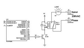
The circuit for controlling a relay with a PIC 16F628 microcontroller consists of a few essential components: the microcontroller itself, the relay, a transistor, a diode, and a power supply. The PIC 16F628 is an 8-bit microcontroller from Microchip Technology that has several input/output pins, including the RB5 pin, which is utilized to control the relay.
In this configuration, the RB5 pin is connected to the base of a transistor, which acts as a switch to control the relay. When the RB5 pin goes high, it sends a signal to the base of the transistor, allowing current to flow from the collector to the emitter. This action energizes the relay coil, causing the relay to switch its contacts and complete the desired circuit.
A diode is placed in parallel with the relay coil to protect the transistor from back EMF generated when the relay is de-energized. This back EMF can damage the transistor if not properly managed. The diode should be oriented such that it does not conduct during normal operation but will conduct when the relay is turned off, providing a path for the inductive kickback.
The power supply for the circuit must be appropriate for the relay being used, as relays typically operate at 5V, 12V, or 24V, depending on their specifications. It is crucial to ensure that the microcontroller and the relay are powered by compatible voltage levels to avoid damage to the components.
Overall, this simple circuit demonstrates the fundamental principles of using a microcontroller to control a relay, showcasing the integration of digital control with electromechanical components in various applications, such as automation and remote switching.Simply you can control a relay through Pic Microcontroller. See a simple circuit for controlling a single relay with pic 16f628. When RB5 port of pic become High the relay will operate. This Circuit works with non-latching ralays(commonly used relays are non-latching) 🔗 External reference
Related Circuits
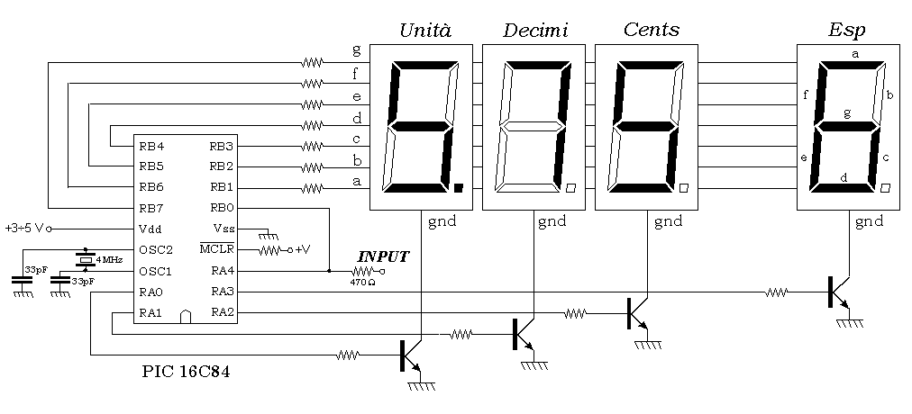
This is a simple 50 MHz auto-ranging frequency meter developed as a course project by Simone Benvenuti and Andrea Geniola. It utilizes a single PIC 16C84 microcontroller and four displays to measure frequencies in the range of 0 Hz...
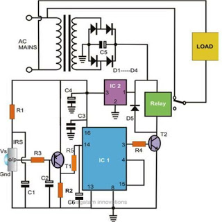
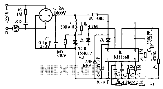
Controlling household electrical gadgets or any electrical equipment remotely can be enjoyable. While using a remote to control devices like a TV or DVD player is a common experience, managing other domestic appliances such as water pumps and lights...
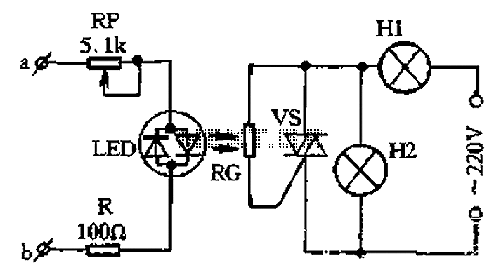
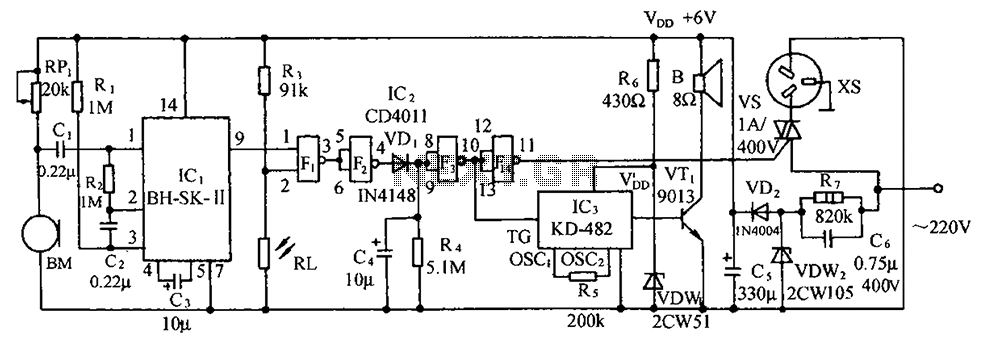
The circuit for a two-color music lantern controller is illustrated in Figure 1-44 below. Terminals a and b are located at both ends of the speaker, which receives audio signals. The audio signal is processed through a sensitivity adjustment...
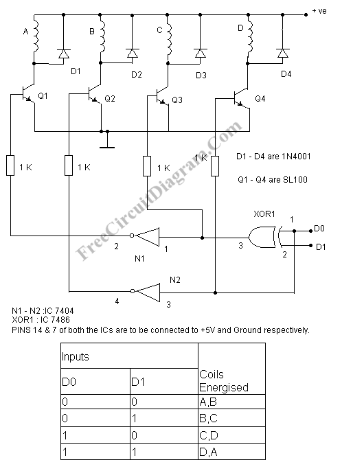
A stepper motor controller is required to operate a stepper motor, as a stepper motor cannot function merely by connecting it to a power supply. A stepper motor controller is an essential component for the effective operation of stepper...
The synchronous vibration circuit operates with a control logic that includes three primary components. An internal oscillator is initiated by a synchronization pulse, transitioning to a low state immediately after the pulse. Upon power activation, the internal circuitry undergoes...
The circuit illustrated includes a sound transducer sensing switch, an electrical light control switch, an SCR control circuit, a vocal music circuit, and an AC step-down rectifier circuit. The circuit comprises several interconnected components that serve distinct functions, allowing for...
Warning: include(partials/cookie-banner.php): Failed to open stream: Permission denied in /var/www/html/nextgr/view-circuit.php on line 713
Warning: include(): Failed opening 'partials/cookie-banner.php' for inclusion (include_path='.:/usr/share/php') in /var/www/html/nextgr/view-circuit.php on line 713