
How to make a Simple Infra Red Remote Control Circuit
This circuit utilizes an infrared (IR) sensor to facilitate remote control of household appliances, enhancing convenience and user experience. The IR sensor, a critical component, is designed to detect infrared signals emitted from a remote control. Upon receiving these signals, the sensor converts them into digital logic pulses. The simplicity of the sensor, with only three leads, allows for straightforward integration into various applications, making it an ideal choice for DIY electronics enthusiasts.
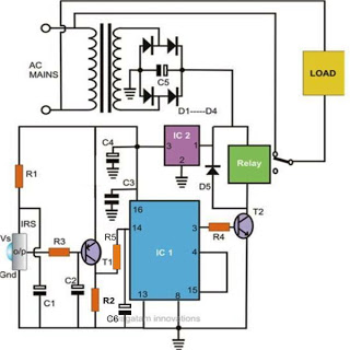
The 7805 voltage regulator is essential for maintaining a stable 5V supply, ensuring that both the IR sensor and the flip-flop IC 4017 operate within their specified voltage ranges. The IC 4017 is a decade counter that can drive multiple outputs based on the input pulse it receives. In this application, it serves as a controller for the connected appliances, with each output corresponding to a specific device.
The use of a PNP transistor (T1) in this circuit plays a crucial role in signal amplification and switching. When the IR sensor detects a signal, it sends a negative pulse that triggers the transistor. This action allows current to flow through resistor R2, creating a positive voltage at the base of the transistor, which in turn activates the flip-flop IC. The output from the IC can be connected to various household appliances, enabling them to be turned on or off remotely.
The entire assembly can be conveniently housed in a small plastic box, providing a compact and organized solution for remote control applications. The design allows for easy access to the output connections, facilitating integration with various electrical devices. This project exemplifies the application of basic electronic components to create a functional and user-friendly remote control system for household appliances.Controlling household electrical gadgets or any electrical equipment remotely can be fun. Controlling gadgets like a TV set or a DVD player through a remote may look pretty common to us and we are very used to with the experience, however for controlling many other domestic equipment like a water pump, lights etc we are compelled to walk around fo r implementing the switching. The article is inspired by our usual TV remote concept and has been applied for controlling other house hold electrical appliances remotely. The circuit facilitates and helps the user to do the operations without moving an inch from his resting place.
Thanks to the highly versatile, miniature IR sensor unit which forms the heart of the circuit and directly coverts the received IR waves from the tranamitter unit into the relevant logic pulses for feeding the fllip flop stage. The sensor basically consists of just three leads viz: the input, the output and the biasing voltage input lead.
The involvmant of only three leads makes the unit very easy to configure into a practical circuit. The sensor is specified for operating at 5 volts regulated voltage which makes the inclusion of the 7805 IC stage important. The 5 voltage supply also becomes useful for the flip flop IC 4017 and is appropriately supplied to the relevant stage.
The PNP transistor T1 responds to the negative trigger pulse from the sensor and quickly pulls the positive potential at its emitter to the collector across the resistor R2. The potential developed across R2 provides a positive logic high to the IC 4017 input pin #14. The IC instantly flips its output and changes it`s polarity. The entire circuit is powered from an ordinary transformer/bridge network and the entire circuit may be housed inside a small plastic box with the relevant wires coming out of the box for the desired connections.
🔗 External reference
Related Circuits
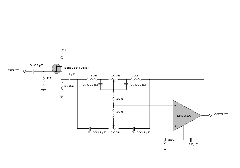
This circuit is a simple series tone control circuit. It utilizes the surgical amplifier LM301A. The JFET 2N3684 provides high input impedance and low noise for the unbuffered operational amplifier, which operates in an equalizer (EQ) configuration. Further details...
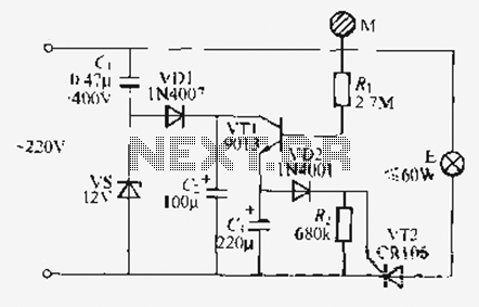
Utilize the call sheet to touch the electrical threshold M, which causes the E lamp to light up. When the same interval subparagraph is triggered, the lights will automatically turn off. A voltage regulator rectifier circuit is formed using...
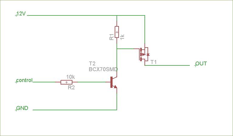
The schematic is attached. Suggestions for improvements are requested, particularly for adding reverse polarity connection protection. The logic level inputs (5 V) are designed to control two output voltages (12 V) using P-channel MOSFETs. The P-channel MOSFETs are ON...
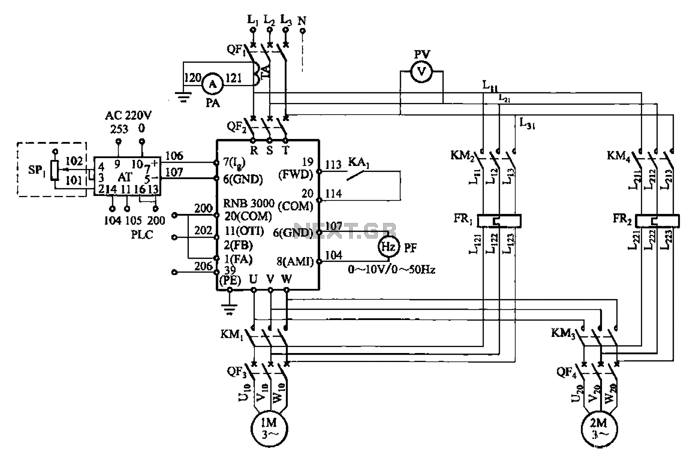
A control circuit for two motors, specifically for frequency control in a constant pressure water supply system, is illustrated in Figure 5-23. The circuit includes fault output terminals labeled 1 and 2, analog feedback current input terminals labeled 6...
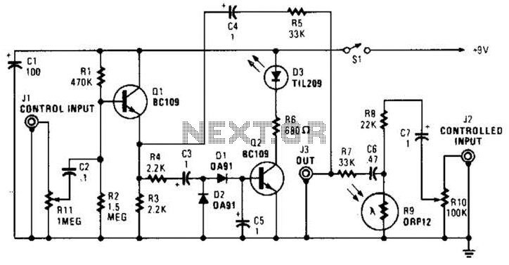
In this circuit, audio input to the control channel is amplified and rectified by diodes D1 and D2. This direct current level activates LED D3 through transistor Q2. The illumination from LED D3 causes R9, a light-dependent resistor, to...
This inverter is designed to operate appliances such as TVs and stereos while traveling or camping. It converts 12 VDC to 120 VAC, with the output wattage determined by the transistors used for Q1 and Q2, as well as...
Warning: include(partials/cookie-banner.php): Failed to open stream: Permission denied in /var/www/html/nextgr/view-circuit.php on line 713
Warning: include(): Failed opening 'partials/cookie-banner.php' for inclusion (include_path='.:/usr/share/php') in /var/www/html/nextgr/view-circuit.php on line 713