
Wire color music lantern controller
The two-color music lantern controller circuit operates by integrating audio signal processing with visual light output, creating an interactive experience that responds to sound. The audio signal is first fed into the circuit via the speaker terminals, where it is conditioned by the potentiometer (RP) to adjust sensitivity levels, allowing for customization based on the environment and audio source. The current-limiting resistor (R) ensures that the current flowing through the LEDs remains within safe limits, preventing damage.
The light-emitting diodes (LEDs) are crucial in this circuit, as they provide the visual feedback that corresponds to the audio input. The optocoupler configuration, which includes the photoresistor (RG), allows for a feedback mechanism where the resistance of RG varies with the intensity of the LED light. This dynamic interaction between the LEDs and RG plays a pivotal role in determining the operational state of the triac, which controls the power delivered to the light bulbs (H1 and H2).
In low audio conditions, the high resistance of RG results in a triac state that allows H2 to receive the majority of the AC voltage, illuminating it in green. Conversely, during high audio conditions, RG’s resistance decreases, triggering the triac to switch off H2 and turn on H1, which glows red. This alternating pattern creates a visually striking effect, enhancing the ambiance of the environment in which the circuit is deployed.
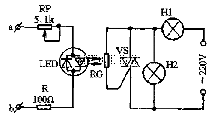
The design of this circuit emphasizes the importance of proper component selection and arrangement to achieve the desired responsiveness and visual effects. The choice of LEDs, the specifications of the potentiometer, and the characteristics of the photoresistor all contribute to the overall performance and efficiency of the music lantern controller. Proper calibration of these components ensures that the circuit can effectively respond to varying audio levels while providing a stable and engaging light display. Circuit wire two-color music lantern controller is shown in Figure 1-44 below. a, b terminals at both ends of the speaker according to the speaker, the speaker from the sound o f the audio signal by the sensitivity adjustment potentiometer RP and current limiting resistor R is applied to both ends of the color light emitting diodes LED to flash with the rhythm of the music. LED and photoresistor RG group into simple optocouplers, so RG resistance with the LED will light off level of change.
When the music sound weak or interrupted when, RG showed a high resistance, the triac trigger voltage vs non-blocking state is due wattage lights on much larger than the group Hl set wattage H2, so most 220V AC voltage landing in H2 ends, so H2 glows green when close to normal, and Hl only a faint red light; when the loud music Shi, LED light. RG showed low resistance, vs AC trigger signal is obtained and opened, then H2 was vs short circuit does not emit light, Hl is normal hair red.
So with the rhythm of the music and downs, Hl, H2 two lights alternately emit light and shade of red, green, two shade.
Related Circuits

Speed regulation is achieved by monitoring the motor current with resistor R17 and utilizing it as positive feedback to offset motor resistance losses. The gain potentiometer should be adjusted to just below the threshold where motor speed begins to...
This low-cost project enables audio reproduction from a television without disturbing others. It eliminates the need for wired connections between the TV and loudspeakers. Instead, it utilizes invisible infrared light to transmit audio signals from the TV to the...
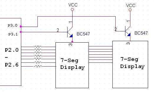
The Tutorial shows how to interface 7-segment display to a microcontroller. Also explains how do display more than one 7-segment on same data lines using scanning method. 7 Seg displays are are basically 7 LED's. It will be much...
A pulse motor, commonly known as a stepper motor, is defined as a motor that changes its excitation state according to input pulse signals, allowing it to move forward at a specific angle or distance. If the excitation state...

An EEPROM is a type of non-volatile memory, which means it is used for permanently storing digital data without any power supply. EEPROM stands for Electrically Erasable Programmable Read-Only Memory. The advantage of this type of ROM is that...
The water resource is being transformed into a valuable and rare commodity. Consequently, promoting water-saving irrigation has become a priority for countries worldwide to address the water resource crisis and achieve agricultural modernization. This text proposes a cipher scheme...
Warning: include(partials/cookie-banner.php): Failed to open stream: Permission denied in /var/www/html/nextgr/view-circuit.php on line 713
Warning: include(): Failed opening 'partials/cookie-banner.php' for inclusion (include_path='.:/usr/share/php') in /var/www/html/nextgr/view-circuit.php on line 713