
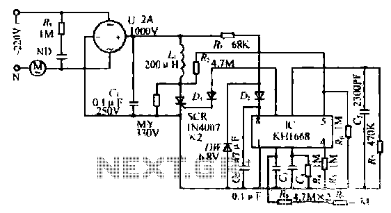
Touch a fan speed control circuit
The synchronous vibration circuit is designed to manage various operational states through a control logic that incorporates an internal oscillator and a frequency division mechanism. This oscillator is triggered by a sync pulse, which resets the internal circuitry and transitions the output to a low state. The circuit is equipped with a touch-sensitive interface that allows users to initiate actions by making contact with designated points, effectively controlling the oscillation frequency for counting purposes.
The SCRs within the circuit play a crucial role in regulating the conduction angle, which directly influences the output characteristics. When a user touches the input, the counter oscillation circuit is activated, and the SCR conduction angle adjusts accordingly. The first touch results in a minimal conduction angle, while subsequent touches increase the angle, allowing for fine-tuning of the output signal.
For remote operation, the circuit can be activated through a metal ring that triggers the necessary touch points, facilitating versatile control options. The power supply is managed through a buck regulator, ensuring that voltage levels remain stable despite variations in input. The output voltage is filtered to provide a steady 6-8V supply, which is essential for the reliable operation of the internal components.
The internal clock, created by resistive and capacitive elements, oscillates at approximately 1.5 kHz, providing the necessary timing for the frequency divider circuit. This clock signal is synchronized with the SCR control, allowing for precise adjustments to the output based on the zero-crossing reference point. Additional filtering components are incorporated to enhance stability and mitigate interference, ensuring that the circuit operates effectively without disruption from external noise or transient signals.
Isolation techniques are also employed to protect the integrated circuit from high-level pulses, which could otherwise cause damage. The design includes an RF-filter network utilizing inductance and capacitance to minimize electromagnetic interference, promoting reliable performance in various operational environments. Overall, the synchronous vibration circuit is engineered for precision control and stability, making it suitable for applications requiring meticulous timing and responsive operation.Synchronous vibration Ai, a liter zygomatic count number, control logic i NIE armpit three parts. Internal oscillator start-up Ai Road [U l: zero just after the sync pulse. Stop Ding Zhen sync pulse close to the lower porphyrin 0:00. Just when the power is turned on, the internal circuitry is automatically reset. (7) feet without pulse output flI. Place under a low state. (2) Debate 1 foot by touch, dividing counter oscillation circuit King J pulse counting, pulse to the first seven. (7) jump to my feet L level until the sync pulse intersection near zero returns low. SCR conduction angle is small. When the second touch by frequency dividing counter circuit for counting the oscillation pulses to the reed 5 (7) feet l 'jump is high almost.
SCR conduction angle is large. 3 gang touch by mf, dividing the first oscillation circuit counting the pulse count. (7) feet Ji jump for the business level, well maintained to ridicule step closer to the zero-crossing pulse. SCR conduction angle on the largest, escape 1500 Tsui. When the fourth by touch, servant-frequency circuit to stop counting II: count (7) feet without pulse output out, equivalent pod machine tune its procedures meet the above-mentioned four-cycle arrest operation carried out.
If the IC (4) feet then the power is extreme, just above the 3.4 leather-like trigger change for completion on / off function. It can touch a metal ring so that M (2) foot touches the world, you can also add high pulse f3) feet it now feast conversion, this feature can be J {{for remote operation.
To f SCR can bared ridicule speed, full bridge U unipolar into the AC ripple voltage. Supply lC K111668 cedar wine container stream power is limiting resistor R3 buck regulator _ Regulators diode D t save 6 8V. Two rice tube D. isolation. After filtering G win 1 6V steady stream of voltage supply. By the resistive and capacitive elements R7. C5 constituting the inner clock oscillation frequency of about 1.5kl-lz, the internal supply output section, counting the frequency divider circuit.
The Ri. R Shu provide back pressure 100} Iz red spine synchronization input to lC VJ (5) feet, counting the internal oscillator and divider circuit and power supply frequency synchronization, the zero crossing of the reference yield canthus' E shift pulse output to change SCR conduction angle, up to date flat motor speed of the wind changes. Touch the end of the two-jH4.7M Cl (f <J resistor in series: j "type, anti-topiramate separated by a short circuit occurs -H resistance shock, 0 for eliminating interference, C3 for filtering to improve the stability .D, used.
circuit isolation, to prevent high -level pulse Ha Chong damage IC. wherein the inductance L and capacitance C. illustrates an RF-filtered network. tfSCR prevent clutter conducting high transient l Bute produced radiate, scrambling around 1 normal operation of electrical equipment;
Related Circuits
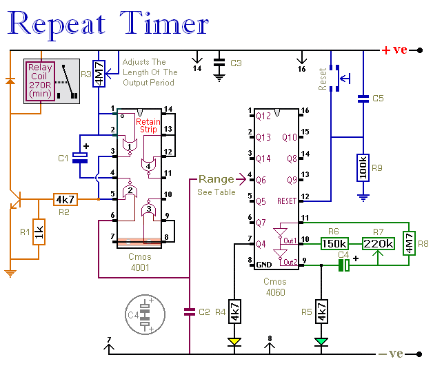
The CMOS 4060 integrated circuit (IC) features two built-in inverters located at pins 9, 10, and 11, which must be interconnected to create an oscillator. The output of this oscillator is available at Pin 9, which continuously alternates between...
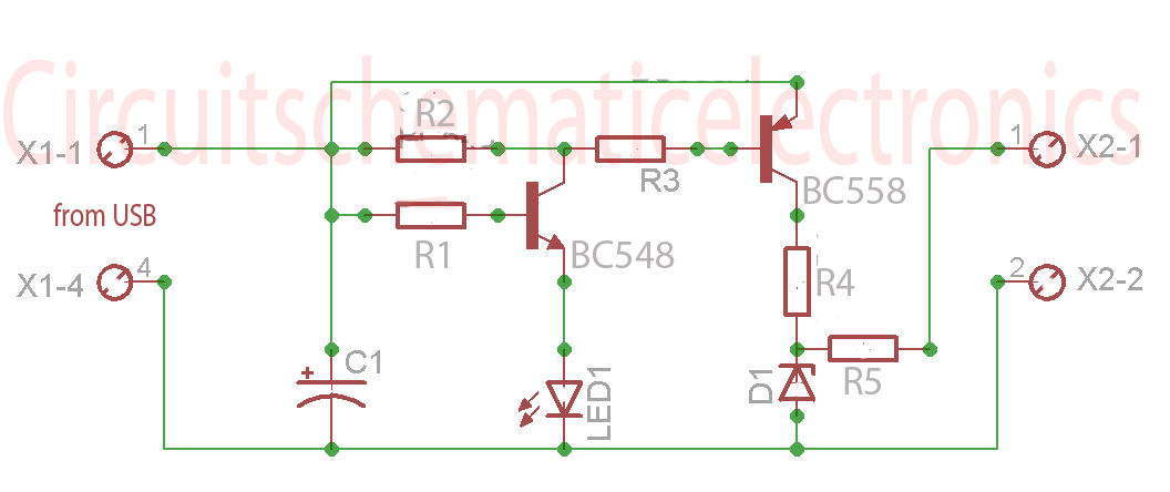
Without a USB to phone battery charger circuit, charging a phone battery using a USB port on a computer can quickly damage the battery, resulting in bulging. This occurs because the voltage output from USB is 5 volts, while...
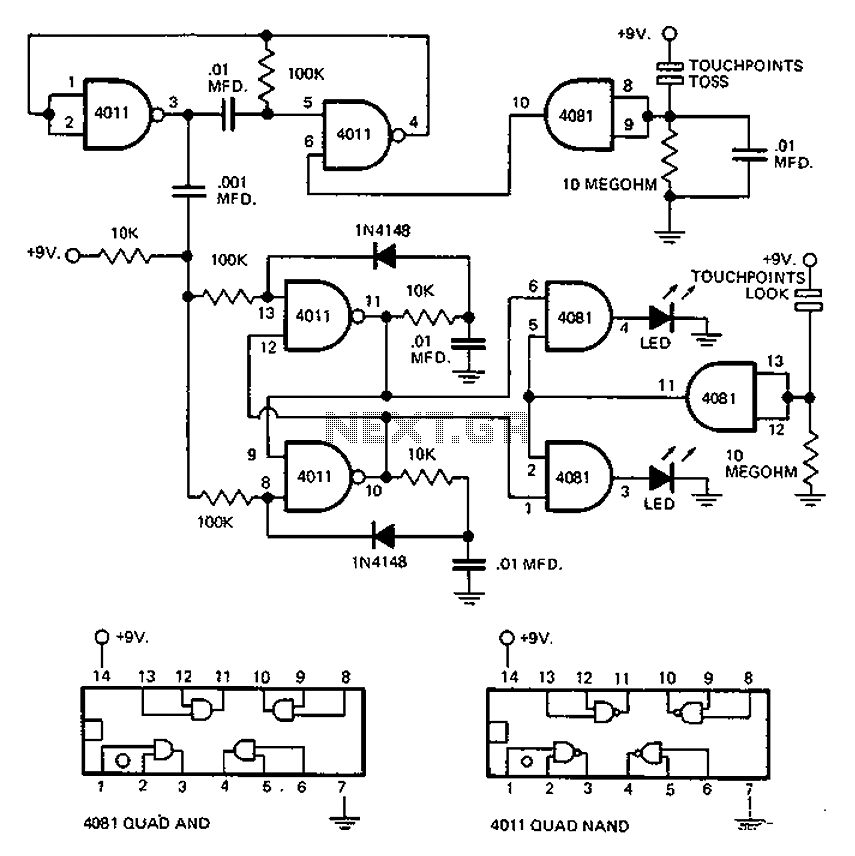
This circuit employs an astable multivibrator to alter the state of a signal based on specific conditions. It also incorporates a flip-flop, which retains the state of the output once a change is detected, completing a cycle of the...
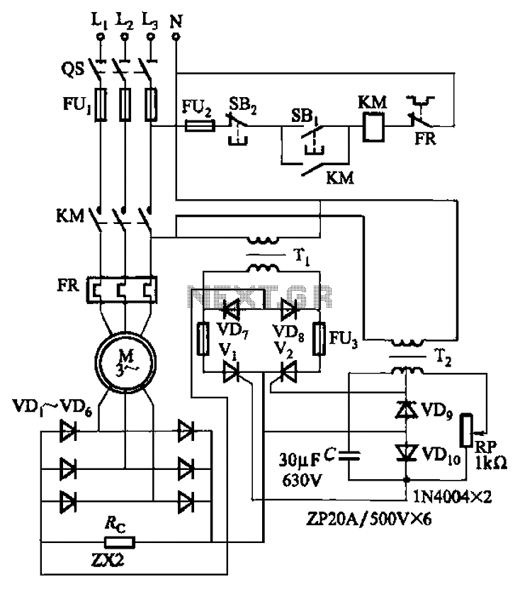
The circuit depicted in Figure 3-171 includes an auxiliary power supply that operates on single-phase AC power. It features a single-phase half-wave controlled bridge composed of diodes VD7, VD8, and thyristors V1, V2. The output current is managed by...
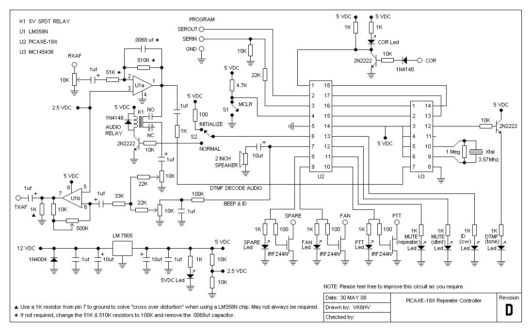
The project involves testing the capabilities of a PICAXE-18X chip operating at 4 MHz for a specific application. It includes designing the circuit, creating printed circuit board (PCB) artwork, etching the PCB, programming the PICAXE in BASIC, and connecting...
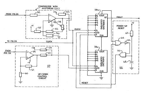
This motor overload circuit allows for short-term overdriving of a system, which is dependent on heat buildup. An overload detection circuit safeguards the motor against currents exceeding the rated current for specific exposure durations. The permissible exposure times are...