
control electric appliances

In a scenario where the initial password 1234 is changed to 5678, the user can arm relays 1, 3, and 4 while disarming relay 2. Additionally, by sending the command <Status>, the user can request the current status of the eight switches and the four relays. In an alternate case, the user may bypass the <Relay> command by directly specifying the relay number and its desired state, such as arming relays 1, 3, and 4 while disarming relay 2, and subsequently requesting the status.
This circuit integrates various components and commands to facilitate remote control and monitoring of devices, enhancing both convenience and security in home automation applications. The use of a microcontroller and GSM module allows for versatile communication and control, making it suitable for a wide range of electronic devices.With this circuit you can power-ON or Power-OFF a lot of electric/electronic devices such as aDSL modem, personal computers, water boilers, water pumps, garage doors, lights and many more. Moreover, you can watch the status of 8 switches. These switches can be connected with reed switches to the windows and the doors of your house. Just like a sec urity system. This circuit is constituted by an AVR micro-controller (ATtiny2313) at 4MHz, the GM-47 GSM module, a SIM card and 4 relays. The GM-47 module works at 3. 3V and is powered by the voltage stabilizer IC1. The micro-controller IC2 can work with power from 2. 7V-5. 5V when the speed is under 10MHz. So we power it at 3. 3V because this is the voltage level that works GM-47 module. The data connection between GM-47 and ATtiny2313 is done at 9600 bps. The voltage level for this comunication is 3. 3V from AVR`s side and 2. 7V from GM-47 side. Because of this voltage difference I used the T2 transistor to do the voltage level adaptation. The connection of the SIM card with the GM-47 is been made by the SIM-holder K15 and the presence of the SIM card into the SIM-holder is been made by the swich SW on SIM-holder.
The LED D6 when it flases, indicates that the connection to the cell phone network has been done properly. When the module cannot been connected to any cell phone network, the LED stays always ON (it`s not blinking).
After you power-on the circuit the IC2 (ATtiny2313) waits until GM-47 is initiallized, by reading the SIM card and connects to the GSM network that SIM card supports. After the connection to the network, the AVR sends the command
If the answer of the module is not
This is done to make the SMS smaller to be handled easiest by the AVR. The next command is
Obviously, your SIM card must have credits to send SMS! In case A we have the maximum of selections. We send the initial password 1234 and we change it to 5678. We arm the relay-1, relay-3, relay-4 and disarm the relay-2. Moreover, by writing the word
Related Circuits
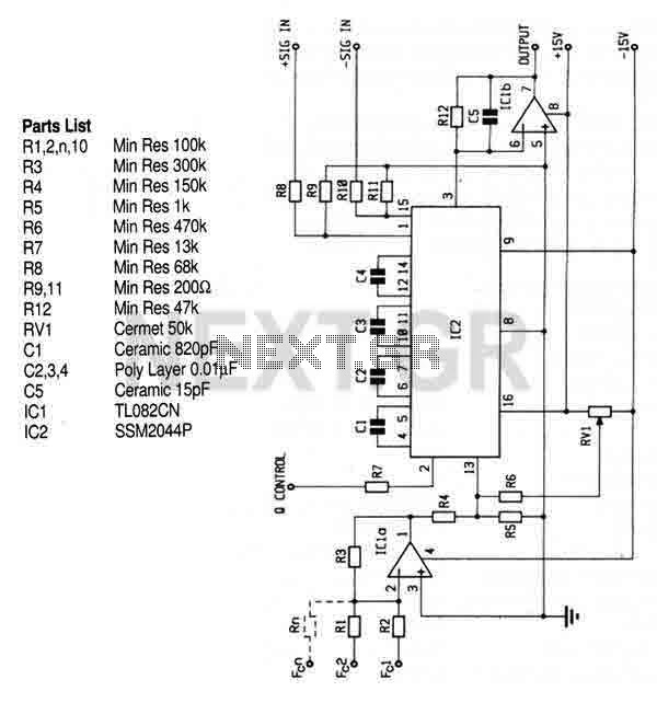
This circuit utilizes the SSM2044 integrated circuit (IC), which is a four-pole voltage-controlled filter specifically designed for electronic music applications. The on-chip voltage control of resonance facilitates straightforward interfacing with programmers and controllers. The IC is characterized by an...
This relay circuit is controlled by nearly any type of infrared remote controller. It operates under the assumption that most remote controllers utilize high-frequency modulated infrared light. By filtering out unmodulated or low-frequency modulated signals, this circuit effectively eliminates...
The VNGBOX microcontroller must generate a precise, high-resolution, and low-noise DC control voltage to accurately steer the reference oscillator phase. Any noise on this signal can introduce noise to the reference, and any non-linearity, particularly unexpected steps in the...
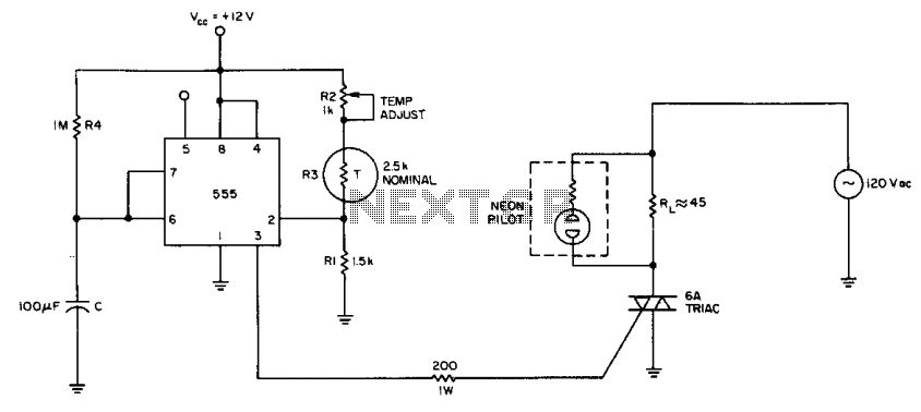
The internal comparator of the 555 timer, combined with a thermistor, creates a low-cost temperature controller. Resistor R2 establishes the temperature trip point. The 555 timer is a versatile integrated circuit widely used in various applications, including timers, oscillators, and...
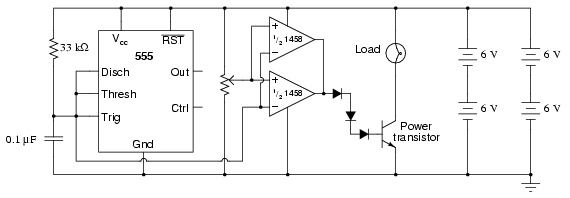
This circuit utilizes a 555 timer to generate a sawtooth voltage waveform across a capacitor, which is then compared to a steady voltage provided by a potentiometer using an operational amplifier (op-amp) configured as a comparator. The comparison of...

The miniature transmitter module, measuring 34 mm x 29 mm x 10 mm, is designed to operate all remote control receiver-switch combinations outlined in this project. A compact 9-volt PP3 battery can be utilized with the transmitter, which is...