
Control Electrical Appliances Using PC Circuit
The described circuit utilizes the parallel port of a PC, specifically leveraging the data lines D0 to D7 for control applications. The primary function of this setup is to allow a PC to control multiple devices (up to eight) through the use of software that interfaces with the printer port. Each of the data bits corresponds to a specific control line for the connected devices, enabling straightforward binary control.
In the schematic, the circuit is designed around a single device controlled by the D0 data line, which is connected to pin 2 of the 25-pin parallel port. To extend control to additional devices, similar circuits must be constructed for each of the remaining data lines (D1 to D7), which correspond to pins 3 through 9 of the parallel port.
The inclusion of an opto-coupler in the design is a critical aspect, as it provides electrical isolation between the PC and the relay driver circuitry. This isolation is important for protecting the PC from potential voltage spikes or noise generated by the connected devices. The opto-coupler allows the control signal from the parallel port to safely trigger the relay, which can then switch higher power loads without risking damage to the PC.
In practical applications, each relay can be configured to control various equipment such as lights, motors, or other electronic devices. The software running on the PC can send signals to the parallel port, which are interpreted by the interface circuit to activate or deactivate the relays as required. This setup is beneficial for automation tasks, remote control applications, or any scenario where multiple devices need to be managed from a central PC system.
Overall, this circuit provides a versatile and effective means of controlling external devices using a standard PC printer port, with the added safety of isolation through the opto-coupler.Here is a circuit for using the printer port of a PC, for control application using software and some interface hardware. The interface circuit along with the given software can be used with the printer port of any PC for controlling up to eight equipment .
The interface circuit shown in the figure is drawn for only one device, being controlled by D0 bit at pin 2 of the 25-pin parallel port. Identical circuits for the remaining data bits D1 through D7 (available at pins 3 through 9) have to be similarly wired.
The use of opto-coupler ensures complete isolation of the PC from the relay driver circuitry. 🔗 External reference
Related Circuits
A straightforward method to create a speaker transformer involves winding turns around a ferrite rod. The primary winding consists of 300 turns of 0.01mm wire, which is very fine, wound over the secondary and concluding with a loop of...

Three power levels are provided by the two logic inputs of this enhanced circuit. R5, D4, D5, and O2 create a power supply for the logic integrated circuit. These components can be excluded if an alternative low voltage source...
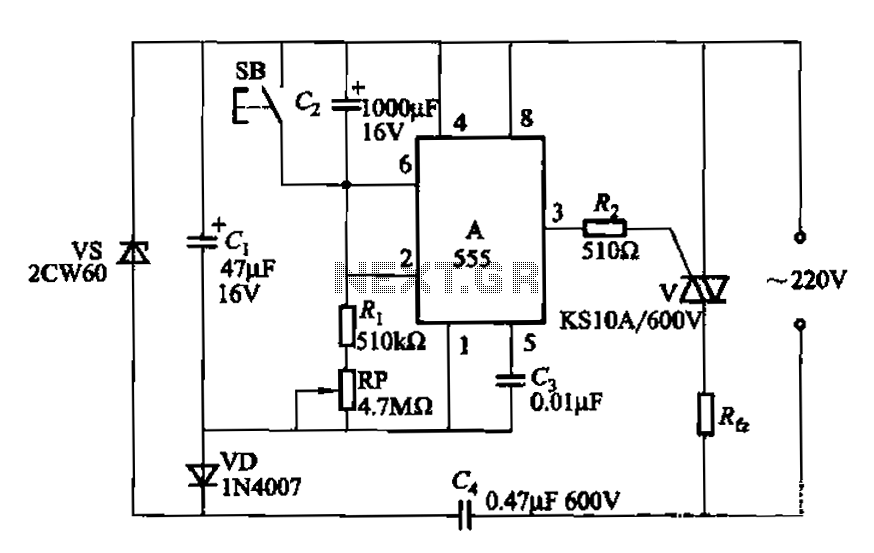
The circuit utilizes a 555 Integrated Circuit (IC) configured as a delay circuit. It transitions from a low to a high state after a button (SB) is pressed, initiating a delay before the output terminal goes high. The output...
The UTC7642 is designed for use in low voltage portable radio cassette systems and other wireless AM systems. It is packaged in a TO-92 casing. The manufacturer is LianShun Electronics Co., Ltd. The UTC7642 is a low-voltage operational amplifier...
It is entirely feasible and acceptable to control various outputs while sitting at a PC terminal. A simple hardware circuit and software are utilized to interface with a 7-segment rolling display. The printer port of a PC provides a...
The induction coil detects the magnetic field flux during phone calls, amplifies the signal, and triggers the LED. These circuits are designed for the phone to rest on the pickup coil. The electromotive force (emf) from the bell electromagnets...