
Simple Remote Control Tester

In this circuit design, the primary function is to detect infrared signals emitted by a remote control and visually indicate this detection through LED D1. The BP103 phototransistor acts as a sensitive receiver for infrared light, which is typically used in remote control devices. When the remote control is activated, it emits infrared signals that are not visible to the human eye. The BP103 detects these signals and produces a corresponding electrical signal.
The BC558 transistor is used as a switching device in this configuration. When the BP103 detects infrared light, it conducts, allowing current to flow to the base of the BC558. This action turns on the BC558, enabling it to drive LED D1, causing it to flash in response to the incoming infrared signal. This visual feedback allows users to confirm that the remote control is functioning and that the infrared signal is being received correctly.
The sensitivity of the circuit can be adjusted using a preset resistor. This component allows for fine-tuning of the circuit's response to varying levels of infrared light, ensuring that the system can detect even weak signals while avoiding false positives from ambient light sources.
In summary, this circuit effectively demonstrates the interaction between infrared light detection and visual indication, utilizing a phototransistor and a bipolar junction transistor to create a simple yet functional remote control indicator. Proper assembly and calibration of the circuit components are essential for optimal performance and reliability.Nearly always when a remote control doesn`t work, the underlying problem is elementary: the unit does not emit light. The cause may be dry solder joints, defective LEDs etc. , but also a flat battery (perhaps due to stuck key). The human eye is unable to perceive infra-red light. By contrast, an ordinary photo transistor like the BP103 has no probl ems working in the infrared spectrum, so in the circuit here it simply biases the BC558 which, in turn, makes LED D1 flash in sympathy with the telegram from the remote control. The preset in the circuit determines the sensitivity. 🔗 External reference
Related Circuits

The timer IC (NE555) is configured as an astable multivibrator in this circuit. It generates an alternating non-sinusoidal output waveform as soon as a supply voltage of 12V is applied. Therefore, alternating voltage is produced from direct current (battery)....

This circuit allows for the testing of quartz resonators within a frequency range of 32 kHz to 24 MHz. The operational status of the quartz resonator is indicated by a diode signaling an LED and an acoustic signal. The circuit...

The circuit depicted in Figure 3-170 illustrates a wound rotor induction motor operating at various speeds, with a voltage (turn difference frequency EMF) U induced in the rotor. The rotor open circuit voltage is represented as Uo (Us0). A...
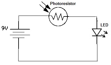
A simple photoresistor circuit will be constructed to demonstrate the operation of a photoresistor, which activates the circuit in the presence of light and deactivates it in darkness. This circuit connects a photoresistor to an LED. When the photoresistor...

One of the more challenging aspects of creating a control or security system that utilizes a PC, such as a burglar alarm, is connecting the sensors to the computer. This typically requires specialized interface expansion boards, and programming that...

A thermistor is utilized in the circuit for heat sensing, while two 5K variable resistors are incorporated to calibrate the circuit for activating the relay at the desired temperature. The inclusion of a 1N4007 diode across the relay serves...