
Control motor PWM schematic
The control of DC motor speed using PWM is a widely adopted practice in modern electronic systems due to its efficiency and precision. In a PWM setup, the average voltage supplied to the motor is effectively controlled by varying the duty cycle of the PWM signal. A higher duty cycle corresponds to a longer ON time, resulting in a higher average voltage and increased motor speed. Conversely, a lower duty cycle reduces the average voltage and slows the motor.
The implementation of PWM can be achieved using various microcontrollers, which can generate PWM signals with precise timing. Alternatively, the IC555 timer can be configured in astable mode to create a PWM signal. In this configuration, the duty cycle can be adjusted by changing the resistance value of the potentiometer (RV1). The IC555 timer operates by charging and discharging a capacitor through resistors, which determines the frequency and duty cycle of the output signal.
For practical applications, the IC555 circuit can be connected to a DC motor through a suitable driver circuit to handle the current requirements. This driver circuit may include transistors or MOSFETs, which can switch the motor on and off rapidly according to the PWM signal, allowing for smooth speed control. It is essential to ensure that the components used in the circuit can handle the motor's current and voltage specifications to avoid damage.
Overall, PWM provides a robust solution for controlling DC motor speeds in various applications, from robotics to industrial automation, enabling precise and efficient motor management.In general there are two ways to control DC motor speed: by varying supply voltage and pulse width modulation (PWM). First control method is not convenient especially in digital systems. It requires analog circuitry and so on. Second motor speed control method is very convenient for digital systems, because all control is made using only digital s
ignals. As you already know PWM (Pulse Width Modulation) is all about switching speed and pulse width (duty cycle). Duty cycle is ratio of signal time ON/T. T is period of signal. In above diagram you see two signals. First duty cycle is about t1/T=1/3 and another`s duty cycle would be about t2/T=2/3. And notice the period of signals are the same. In this way you can control motor speed using microcontrollers PWM output or if you need you may use simple control motor PWM schematic constructed using IC555 timer circuit: Without going too deep in to 555 timer`s performance analysis I can mention that duty cycle can be changed using potentiometer RV1.
The period of signal won`t change as over all resistance between Vcc and 555 pin 6 does not change. We aim to transmit more information by carrying articles. Please send us an E-mail to wanghuali@hqew. net within 15 days if we are involved in the problems of article content, copyright or other problems. We will delete it soon. 🔗 External reference
Related Circuits
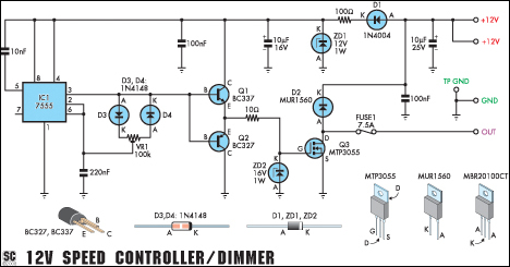
This versatile circuit functions as a speed controller for a 12V motor with a continuous rating of up to 5A or as a dimmer for a 12V halogen or standard incandescent lamp with a maximum rating of 50W. It...
C0QBmk~%24(KGrHqIOKkIEq4M%2Bu,)1BK2zHH580Q~~_35.gif)
This time, information will be shared about the schematics of radios, specifically the schematic of a programmer radio, along with the latest information available on Onmilwiki. The schematic of a programmer radio typically includes various components essential for its operation,...
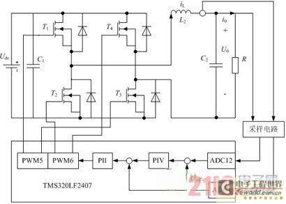
Traditional UPS systems use analog circuit control, which presents significant limitations for both manufacturers and users, regardless of whether they employ technology or SPWM technology. With advancements in information technology, the introduction of high-speed digital signal processing chips, known...

The audio mixer schematic proposed is developed around four amplifiers built inside the SSM2024 produced by Precision Monolithics Inc. (PMI) and is voltage-controlled (VR). The maximum VR voltage is 5.5 volts. The signal-to-noise ratio is 90 dB, and the...
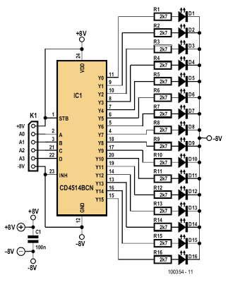
The indicator described here is specifically designed for adjusting the dynamic limiter outlined elsewhere in this edition and checking if the maximum level of the reference voltage (P1) requires modification. A 4-to-16 decoder integrated circuit (IC) of type 4514...
The VCA project demonstrates the use of the VCA_Setup and VCA_Data components in ADS. These components belong to the ADS behavioral model suite located under the System - Data Models palette. The schematic "Amp_wBothMatches_setup.dsn" is designed to extract circuit-level...