
12v speed controllerdimmer
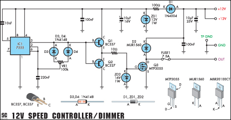
The circuit utilizes a PWM technique to modulate the voltage applied to the load, allowing for precise control over the speed of the motor or the brightness of the lamp. The key components typically include a microcontroller or a dedicated PWM controller IC, a MOSFET or transistor for switching, and necessary passive components such as resistors and capacitors to filter and stabilize the PWM signal.
For a 12V motor, the circuit can efficiently manage the motor's speed by adjusting the duty cycle of the PWM signal; a higher duty cycle results in increased speed, while a lower duty cycle slows the motor down. The circuit should be designed to handle the thermal and electrical characteristics of the motor, ensuring that the switching device can manage the continuous current without overheating.
When used as a dimmer for lamps, the circuit similarly adjusts the brightness by varying the average power delivered to the lamp. It is crucial to ensure that the PWM frequency is suitable for the type of lamp used, as some lamps may flicker at certain frequencies. The 220Hz frequency is generally effective for most incandescent and halogen lamps, providing smooth dimming without visible flicker.
Overall, this circuit is a practical solution for applications requiring variable speed control or brightness adjustment, making it suitable for various electronic projects and industrial applications. Proper design and implementation are essential to ensure reliability and performance under the specified load conditions.This handy circuit can be used as a speed controller for a 12V motor rated up to 5A (continuous) or as a dimmer for a 12V halogen or standard incandescent lamp rated up to 50W. It varies the power to the load (motor or lamp) using pulse width modulation (PWM) at a pulse frequency of around 220Hz..
🔗 External reference
Related Circuits
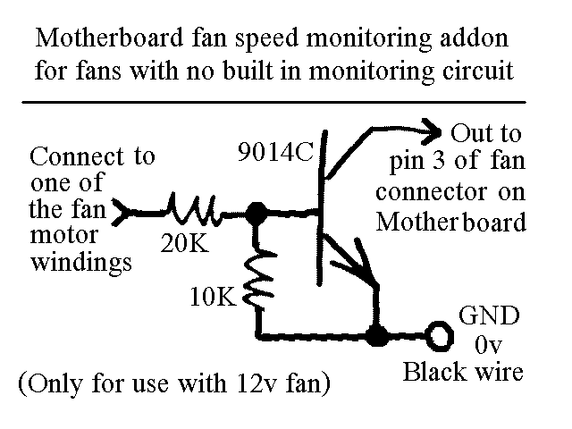
You will find this identical circuit inside most 3 wire computer fans with speed monitoring output to the motherboard. Peel off the sticker from the fan hub in order to access a motor winding pin for connecting up the...
A NOS lathe is available, but it lacks any historical information. It appears to be purpose-built, and it is important to note that there is no available technical support for this equipment. The absence of historical context for the NOS...
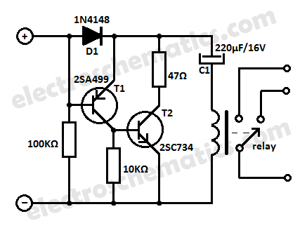
Protect your equipment with this compact 12V time delay relay circuit. The SMPS-based power supply of modern electronic devices is susceptible to voltage spikes. This 12V time delay relay circuit is designed to safeguard sensitive electronic devices by providing a...
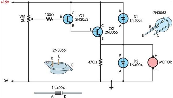
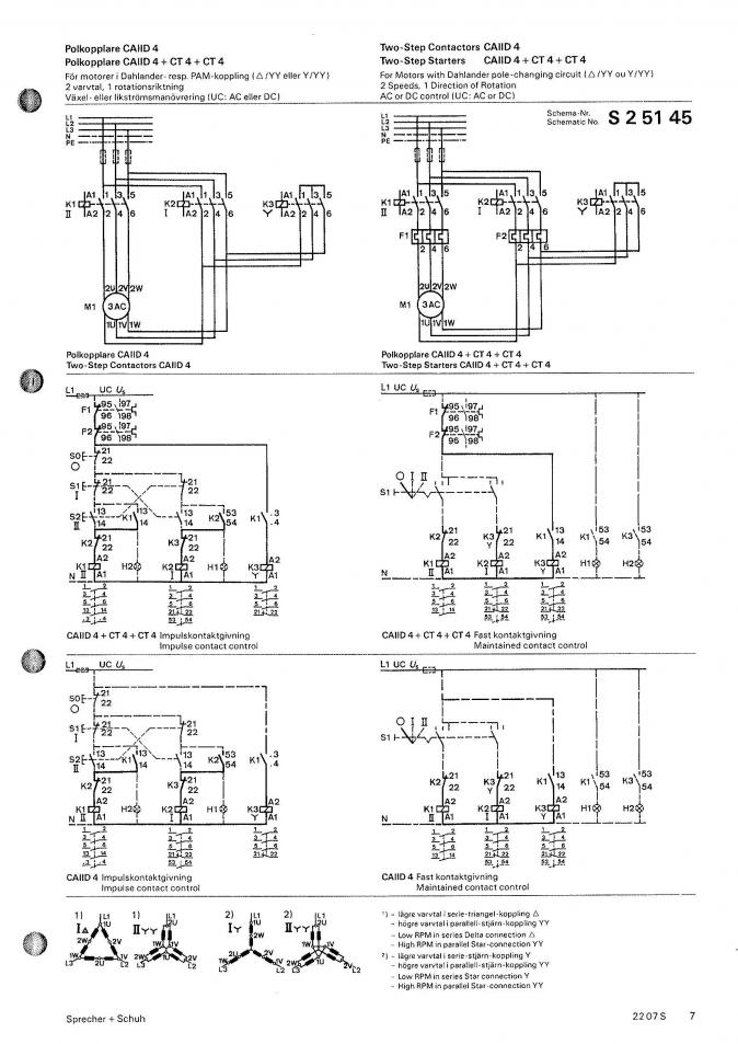
Two simple 12V DC motor speed controllers can be constructed for a minimal cost. These controllers take advantage of the principle that the rotational speed of a DC motor... DC motor speed controllers are essential components in various applications where...
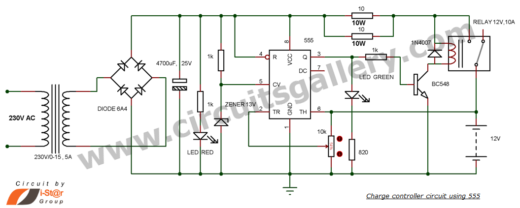
This is a simple DIY charge controller schematic created in response to a request from one of the readers on our Facebook page. The primary component of this automatic battery charger circuit is a 555 timer, which compares the...
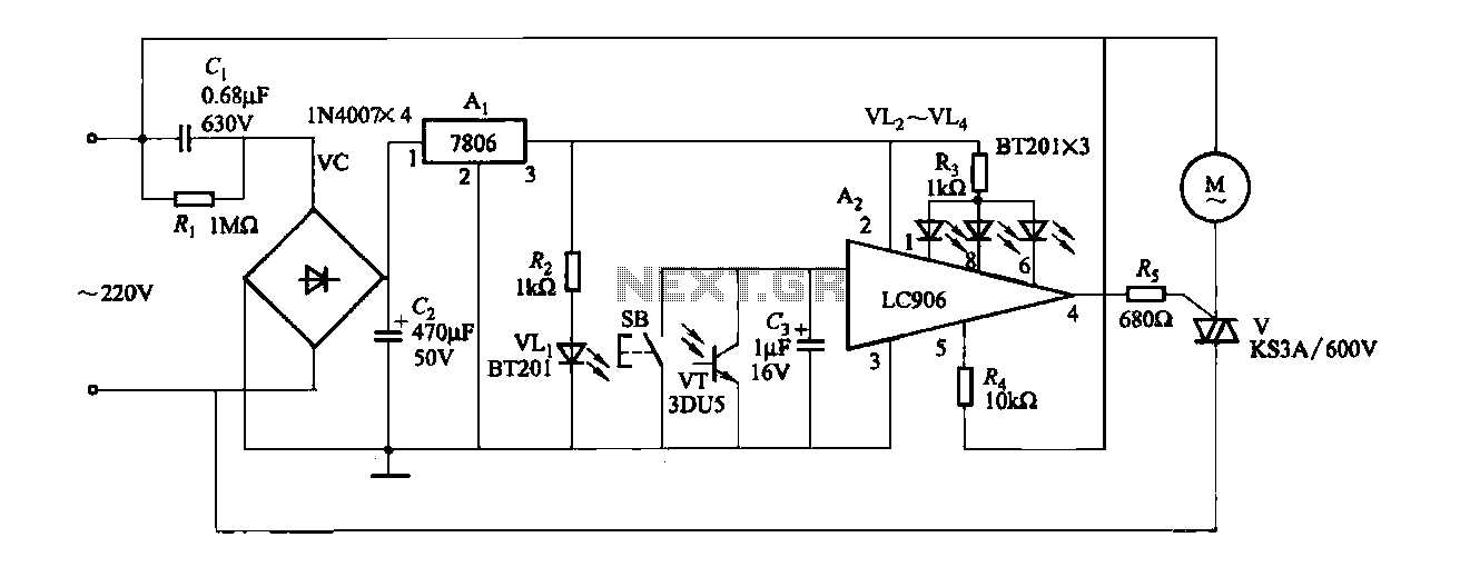
The ceiling fan speed control circuit depicted in Figure 3-6 utilizes a capacitor step-down method and a three-terminal fixed 7806 voltage regulator. It achieves fan speed control through the integrated circuit A2, which regulates the conduction angle of the...