
Data Based Voltage Controlled Amplifier
This project utilizes the VCA_Setup and VCA_Data components to facilitate various types of simulations within the Advanced Design System (ADS). The VCA_Setup component is responsible for establishing the parameters required for the simulations, while VCA_Data processes the results generated from these simulations.
The schematics included in the project serve specific purposes. "Amp_wBothMatches_setup.dsn" acts as the foundational setup for circuit extraction, enabling the retrieval of essential circuit-level data from "Amp_wBothMatches_subnet.dsn." This data is critical for subsequent behavioral simulations.
The "Amp_wBothMatches_circuit_1tone.dsn" schematic implements a one-tone swept control voltage and input power harmonic balance simulation, allowing for detailed analysis of the amplifier's performance under varying input conditions. The results from this schematic provide insights into the frequency response and stability of the circuit when subjected to different control voltages.
For behavioral simulations, "Amp_wBothMatches_behavioral_1tone.dsn" utilizes the previously extracted data to perform a similar one-tone swept analysis, but from a behavioral perspective. This approach allows for a broader understanding of how the amplifier behaves under different operational scenarios, particularly when considering non-ideal conditions.
The envelope simulations are handled by "Amp_wBothMatches_circuit_env.dsn" and "Amp_wBothMatches_behavioral_env.dsn," which focus on the circuit's response to varying envelope signals. These simulations are essential in communications applications where the signal envelope plays a critical role in performance.
The results from these various simulations are stored in designated datasets, providing a structured approach to data management within the project. The comparison illustrated in Figure 1 emphasizes the importance of appropriate sampling rates, as the findings indicate that a sampling strategy of 2 V and 4 V fails to adequately represent the circuit's behavior at intermediate control voltages, such as 3 V. This highlights the need for finer sampling in order to capture the nuances of the circuit's response accurately, thereby ensuring reliable and effective design outcomes.The VCA project illustrates the use of the VCA_Setup and VCA_Data components in ADS. These components are part of the ADS behavioral model suite found under the System - Data Models palette. "Amp_wBothMatches_setup. dsn" is a schematic for extraction of circuit level information for "Amp_wBothMatches_subnet. dsn. " The result is in the dataset "Amp_wBothMatches_setup. ds" which will be used by VCA_Data for behavioral level simulations. "Amp_wBothMatches_circuit_1tone. dsn" is a schematic for a circuit level 1-tone swept control voltage and swept input power harmonic balance simulation of "Amp_wBothMatches_subnet. dsn. " The result is in the dataset "Amp_wBothMatches_circuit_1tone. ds. " "Amp_wBothMatches_behavioral_1tone. dsn" is a schematic for a behavioral level 1-tone swept control voltage and swept input power harmonic balance simulation of "Amp_wBothMatches_subnet.
dsn" using VCA_Data along with the dataset "Amp_wBothMatches_setup. ds. " The result is in the dataset "Amp_wBothMatches_behavioral_1tone. ds. " "Amp_wBothMatches_circuit_env. dsn" is a schematic for a circuit level circuit envelope simulation of "Amp_wBothMatches_subnet. dsn. " The result is in the dataset "Amp_wBothMatches_circuit_env. ds. " "Amp_wBothMatches_behavioral_env. dsn" is a schematic for a behavioral level circuit envelope simulation of "Amp_wBothMatches_subnet. dsn" using VCA_Data along with the dataset "Amp_wBothMatches_setup. ds. " The result is in the dataset "Amp_wBothMatches_behavioral_env. ds. " In Figure 1, a comparison of circuit and behavioral level results is given for Harmonic Balance simulation. The sampling for VCA_Setup is 2 V, 4 V and 6 V, a 2 V spacing. The deviation for Vcontrol = 3 V illustrates the effect of improper sampling for VCA_Setup. Sampling at 2 V and 4 V is simply too coarse to properly capture the response at 3 V. 🔗 External reference
Related Circuits
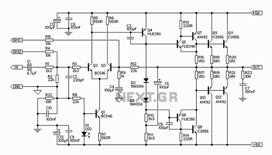
The 300W amplifier circuit presented is a conventional design. It includes connections for the internal SIM and incorporates filtering for RF protection (R1, C2). The input is facilitated through a 4.7µF bipolar capacitor, which offers substantial capacitance in a...
A common collector amplifier circuit structure and its key components are outlined. The composition of the common collector amplifier circuit is fundamentally similar to that of a common emitter amplifier circuit, with two notable exceptions: one is the collector...
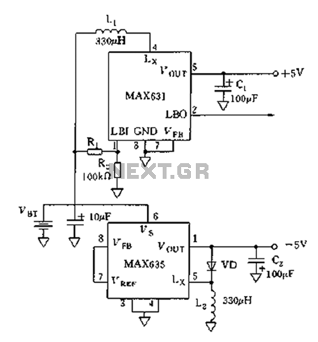
This circuit is a simple design that outputs a voltage higher than the input. It can be used to power 12V or 9V devices from a 6V system or to operate 6V devices from a 1.5V battery. The circuit...
The motion games on the Nokia 5800 sparked an interest in creating a real-world version of a racing car controlled by tilting a phone. The motion-controlled robot, named Hercules due to its high torque and speed, is operated via...
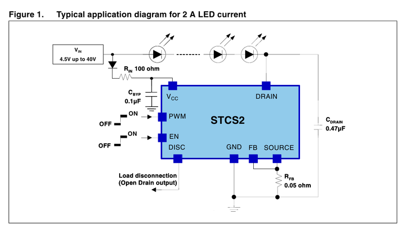
A driver based on the STCS2 for a 445nm laser is being developed. The STCS2 was selected due to its low voltage drop, and the power supply will consist of two lithium-ion cells. The STCS2 is a highly efficient, low-dropout...
Application of the High Power LED Driver SP7652 with an Analog 0V-to-10V dimmer. Electrical Requirements: Input Voltage of 5.5V to 28V, Output Voltage VF of LED, Output Current ranging from 0 to 6A. This circuit is designed to provide...