
Simple Indicator for Dynamic Limiter Schematic Diagram
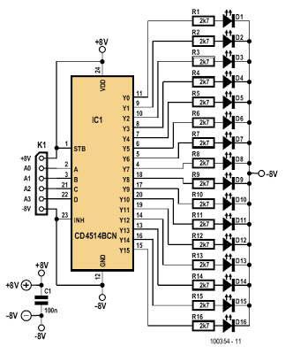
The described indicator circuit serves as a crucial component in managing the dynamic limiter's performance by providing visual feedback through an array of 16 LEDs. Each LED corresponds to specific states of the limiter's operation, indicating varying levels of gain. The 4-to-16 decoder IC (4514) plays a vital role in translating the four-bit counter's output into a format suitable for LED activation. The design ensures that each LED is driven independently, preventing potential issues associated with using a common cathode resistor due to the higher supply voltage.
The arrangement of the LEDs allows for a clear visual representation of the limiter's status, facilitating real-time adjustments. The choice of colors for the LEDs enhances the user interface, allowing operators to quickly identify the operational state of the limiter. The use of red for the maximum gain indicator (D1) and green for the minimum gain indicator (D16) provides an intuitive understanding of the gain range, while yellow LEDs indicate intermediate levels.
Connecting the indicator circuit to the limiter's output via the K5 connector ensures seamless integration, allowing for straightforward monitoring and adjustment of the limiter's performance. The circuit's design accommodates various input sources, making it versatile for different applications. The feedback mechanism provided by the LEDs enables operators to fine-tune the potentiometer P1 effectively. By adjusting P1, operators can ensure that the limiter operates within the desired parameters, preventing distortion and maintaining signal integrity across different input levels.
In summary, this indicator circuit is an essential tool for optimizing the performance of the dynamic limiter, providing clear visual feedback and facilitating precise adjustments to maintain optimal signal levels.The indicator described here is specifically designed for adjusting the dynamic limiter described elsewhere in this edition and checking whether the maximum level of the reference voltage (P1) needs to be modified. Her e we use a 4 -to -16 decoder IC (type 4514) to monitor the state of the four-bit up/down counter in the limiter circuit.
This IC c an be powered from the ±8 V supply voltages of the limiter. The limiter board has a 6-way connector (K5) that provides access to the four counter outputs and the sup-ply voltages. Connector K1 of the indicator circuit can be connected to K5 on the limiter board. One output of the 4514 goes high for each unique 4-bit combination on its inputs, while the other outputs remain logic Low.
A separate current-limiting resistor is connected in series with each LED. It was not possible to use a common cathode resistor here because most LEDs have a maximum reverse blocking voltage of only 5 V, while the supply voltage here (16 V) is a good deal higher. The 16 LEDs ar ranged in a r ow pr ov ide a fluid` indication of the control process. You can enhance the display by using different colours for the first and last LEDs, such as red for D1 (maximum gain) and green for D16 (minimum gain), with yellow for the rest of the LEDs.
While observing signals from various sources (TV set, DVD, media player, etc. ), you can easily use the 16 LEDS to monitor the behaviour of the limiter and adjust the setting of potentiometer P1 in the limiter circuit. It must be set such that D16 only lights up at the maximum signal level. If this is not possible and D16 remains lit a good deal of the time regardless of the position of P1, it will be necessar y to increase the value of P1.
Of course, it is also poss-ible to adjust P1 so the strongest signal source extends slightly above the control range of the limiter. 🔗 External reference
Related Circuits
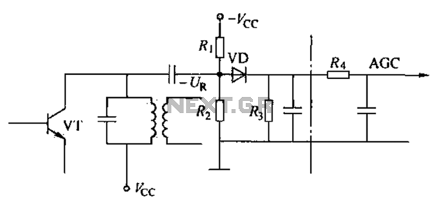
Commonly referred to as an automatic gain control (AGC) circuit, it is primarily utilized in receivers. This circuit maintains a constant output voltage amplitude despite variations in the input signal amplitude. It ensures that the receiver can effectively process...
Quiz-type game shows are increasingly popular on television. In these games, fastest finger first indicators (FFFIs) are used to test players' reaction times. When a player presses their entry button, their designated number is displayed alongside an audio alarm....
In the event of a sudden power failure in an elevator, it is crucial for the duty officer in the distribution room to be alerted promptly to prevent panic among passengers trapped inside. The following describes a sound alarm...
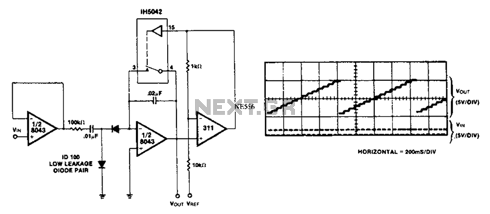
This simple circuit utilizes an LM311 as a level detector, incorporating CMOS analog switches to control capacitance. A significant feature of this counter is its ability to change numbers. The comparator operates more efficiently when there is a need...
The diagram illustrates the principle circuit of a radio control car receiver. Important notes include the selection of transistor Q1, which is specified as either 1815 or 9018, along with the bias resistor R1, which has values of 240K...
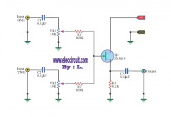
This circuit is a simple mixer circuit that can mix two signal channels into one output channel. It utilizes a codec circuit to convert stereo audio into mono audio. Additionally, the circuit can increase the number of channels by...