
Dc motor speed controller circuit using NE555
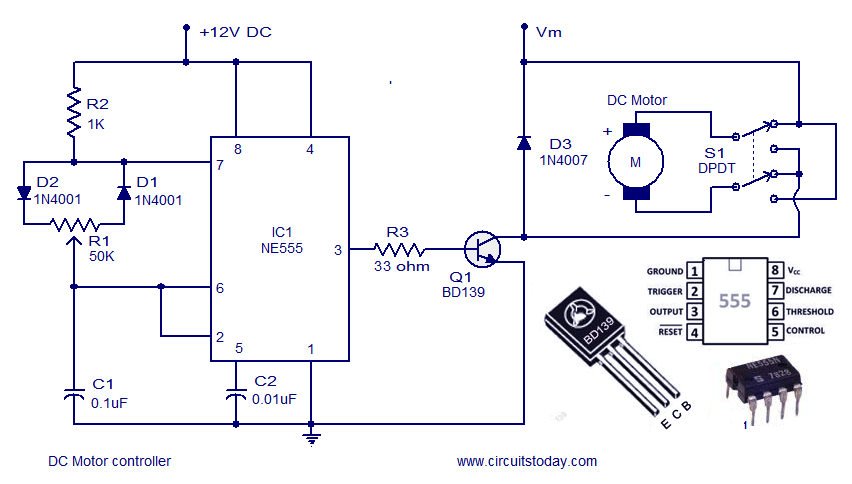
The described circuit utilizes the NE555 timer IC in astable or monostable mode to control the speed and direction of a DC motor. In the astable configuration, the NE555 generates a PWM (Pulse Width Modulation) signal, which is used to vary the average voltage supplied to the motor, thereby controlling its speed. The duty cycle of the PWM signal can be adjusted by changing the resistance and capacitance in the timing network connected to the NE555.
For direction control, an H-bridge configuration is often employed. This arrangement allows the current to flow through the motor in either direction, enabling forward and reverse operation. The control signals for the H-bridge can be derived from the outputs of the NE555 timer or from additional control circuitry, such as a microcontroller or manual switches.
Key components of the circuit include the NE555 timer, resistors, capacitors, an H-bridge driver (such as the L298 or L293D), and the DC motor itself. Proper selection of component values is crucial for achieving the desired speed range and responsiveness of the motor control. Additionally, protective elements like diodes may be included to prevent back EMF from damaging the circuit when the motor is turned off.
Overall, this DC motor controller circuit provides a flexible solution for controlling the speed and direction of a DC motor, suitable for various applications in robotics, automation, and hobby projects.A DC motor controller based on NE555 timer is shown here. Direction of rotation of DC motor can be also changed by this DC motor speed control circuit.. 🔗 External reference
Related Circuits
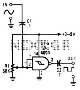
This circuit converts a sine wave into a square wave. It consists of a single 2-input NAND Schmitt trigger configured as an inverter, with an adjustable trigger level at its input. As the input voltage exceeds the gate's trigger...

This simple FM wireless microphone transmitter can transmit speech over a short range. It can be used as a simple cordless microphone. The circuit uses two. The FM wireless microphone transmitter is designed for short-range audio transmission, making it suitable...
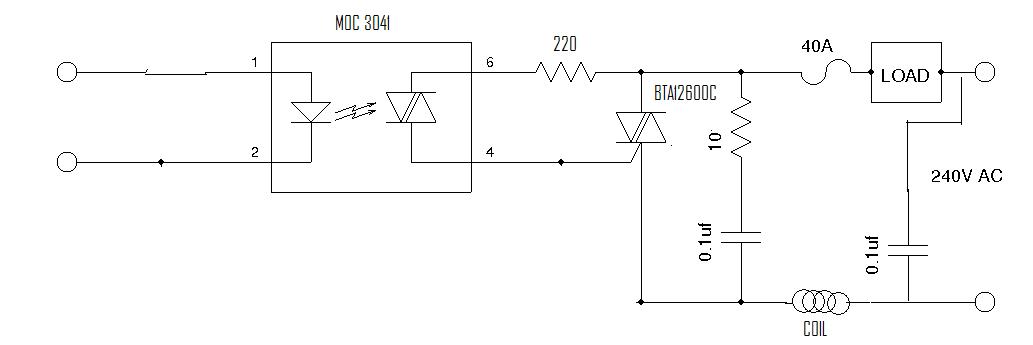
In single-phase AC induction motors, commonly found in refrigerators and washing machines, a start winding is utilized during the initial starting phase. Once the motor reaches a specific speed, this winding is deactivated. The start winding operates slightly out...
Even though the power was off, there was AC present at the handle plug, and a short circuit occurred. Upon disassembly, a blown transistor was discovered. An attempt was made to fix the issue, but after one month and...
Any stepper motor can function as a generator. Unlike other types of generators, a stepper motor generates a significant induced voltage even at low rotational speeds. The specific model used here has a DC resistance ranging from 2 ohms...
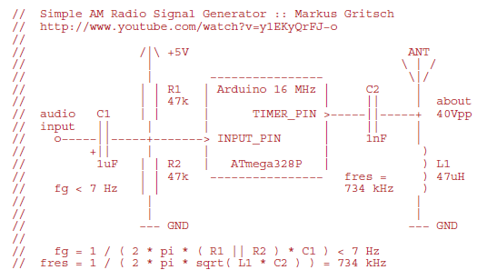
Markus constructed a software AM radio transmitter utilizing an Arduino. The audio signal is supplied to the ADC input via a decoupling capacitor. A PWM output pin directly controls a capacitor-inductor circuit connected to an antenna. The schematic and...