
Controlling a relay with a digital logic level circuit

The schematic encompasses four distinct configurations for relay control using digital logic signals, each tailored to specific operational requirements.
In Figure A, the configuration is optimized for scenarios where the relay coil's current demand is 100 mA or lower, with a minimum input current of 2 milliamps. The resistor (R) is calculated based on the input voltage and the current supplied. This design emphasizes the importance of selecting the correct resistor value to ensure the transistor can adequately drive the relay. The example illustrates the calculation for a 5-volt input, highlighting the process of determining the appropriate resistor value to achieve the desired relay current.
Figure B simplifies the control mechanism when the input voltage matches the relay coil voltage. This configuration eliminates the need for a resistor due to the high input impedance of the emitter follower, allowing for direct control of the relay with minimal input current. The explanation of current division based on transistor gain is crucial for understanding how input and output currents relate in this setup.
Figure C introduces a method for amplifying small input currents, utilizing a dual-transistor arrangement to achieve a significant gain. The option of substituting a Darlington transistor is noted, which would further enhance the gain and efficiency of the circuit. The calculations provided illustrate how to determine the necessary resistor values to maintain functionality with low-power input signals.
Lastly, Figure D demonstrates a method to reverse the relay's operating logic, allowing for engagement with low input signals and disengagement with high signals. The explanation of R1's selection criteria ensures that both transistors operate within their saturation limits, providing a reliable switching mechanism.
Overall, the schematic serves as a comprehensive guide for implementing relay control in various applications, emphasizing the importance of understanding transistor characteristics and circuit configurations to achieve desired operational outcomes.The schematic below illustrates 4 methods of controlling a relay with a digital logic signal. Figure (A) can probably be used in most cases where the relay coil requires 100 mA or less and the input current is 2 milliamps or more. The resistor value (R) is determined from the input voltage and the available current. For example, a 5 volt input sig nal supplying 2 milliamps would require (5-. 7)/. 002 = 2150 ohms, or a 2. 2K standard value. If the transistor has a minimum current gain of 50, there will be 100 mA of current available for the relay coil. The following table shows various resistor values that can be used to obtain various relay coil currents assuming a transistor current gain of 50 such as the 2N3053.
74XX refers to standard TTL logic, 74LSXX refers to low power TTL logic, 74HC is high speed CMOS and CD40XX is the older CMOS devices. The currents given are approximate values and may not be correct for all devices but should be close.
Figure B can be used when the input voltage is the same as the relay coil voltage. The voltage on the emitter of the transistor will be about 0. 7 volts less than the input, so a 12 volt relay would operate on 11. 3 which should be close enough. No resistor is needed since the emitter follower configuration presents a high impedance at the input. The input current will be the relay coil current divided by the transistor gain. For example a 120 ohm relay coil will draw 100 mA at 12 volts and if the transistor gain is 50, the input current will be about 2 milliamps.
Figure C can be used to provide additional gain when the input current is very small. You can also use a Darlington transistor in place of the two transistors which is a better approach, but this idea works just as well when you don`t have a Darlington transistor handy. The overall gain will be the product of the individual gains of the two transistors or about 2500 for two transistor with a gain of 50 each.
This will enable supplying over 250 mA to the relay with only 100 microamps of input current. The R value will depend on the input voltage and current and gain of the first transistor. For example, using a 5 volt input and 100 microamp current and transistor gain of 50, the R value will be 5 minus two diode drops (5 - 1. 4) divided by the input current times 50, or about (5 - 1. 4) / (. 0001 * 50) = about 750 ohms. So this setup can be used when controlling heavy duty relays with low power CMOS logic signals. Figure D can be used to reverse the relay action so that it engages when the input is low and disengages when the input is high.
The R value is determined the same as in Figure A. The R1 value should be high enough to ensure saturation of the first stage and low enough to saturate the second stage. For example, if a 12 volt relay coil requires 100 mA and the driving transistor gain is 50, then the base current will be 100/50= 2 mA and the R1 value must be less than 6000 ohms so that 2 mA does not drop more than the supply voltage of 12.
If the first transistor gain is 50 and the input current is 100 microamps, the collector current will be 5 mA and the R1 value must be greater than 2400 ohms so that 5 mA drops the entire supply voltage of 12. So we need to select something between these two limits of 2. 4K to 6K, something around 4. 3K would be near the midrange. 🔗 External reference
Related Circuits

A Field Effect Transistor (FET) is an amplifying device where the output current is influenced by the input voltage. The FET preamplifier described here is sensitive. The Field Effect Transistor (FET) operates by utilizing an electric field to control the...
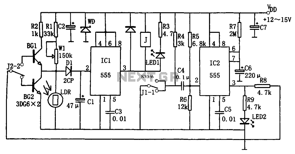
The optical control circuitry for high-performance street lighting is depicted in the figure. The circuit comprises a photoelectric conversion element, specifically a Light Dependent Resistor (LDR), a comparator circuit using an integrated circuit (IC1) which is a 555 timer,...
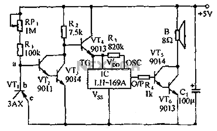
The circuit consists of a temperature sensor, electronic switches for temperature control, and a vocal language output system. During hot summer months, the central processing unit (CPU) of PCs frequently experiences overheating. The circuit, with VT1 positioned near the...
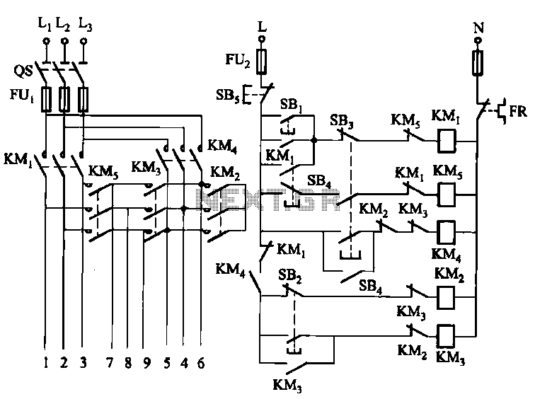
The circuit illustrated in Figure 3-62 is a manually controlled step-down start button circuit. Upon startup, the initial motor windings are configured in a Y-shape. Subsequently, the configuration transitions to a Yanbian shape (2:1), followed by a Yanbian shape...
This sound level meter serves as an effective one-chip replacement for standard analog meters. It is entirely solid-state, ensuring durability and longevity. The circuit is built around the LM3915 audio level integrated circuit (IC) and requires only a minimal...
The transmitter described here includes an additional RF power amplifier stage following the oscillator stage, which increases the output power to 200-250 milliwatts. When connected to a properly matched 50-ohm ground plane antenna or a multi-element Yagi antenna, this...
Warning: include(partials/cookie-banner.php): Failed to open stream: Permission denied in /var/www/html/nextgr/view-circuit.php on line 713
Warning: include(): Failed opening 'partials/cookie-banner.php' for inclusion (include_path='.:/usr/share/php') in /var/www/html/nextgr/view-circuit.php on line 713