
Controlling high-current circuits
The digital output from a microcontroller, typically characterized by low-amperage signals, is essential for interfacing with various electronic components. The microcontroller's output pin can be set to HIGH, resulting in a voltage of either +3.3V or +5V, and a current limit of approximately 10 milliamps. This output is sufficient for low-power devices like LEDs, but many applications necessitate controlling devices that draw more current.
To bridge the gap between the microcontroller and higher current devices, components such as relays and switching transistors are employed. Relays function as electromechanical switches that can be activated by small currents. The principle of operation involves generating a magnetic field through a coil when current flows, which then moves an iron shaft to open or close a switch. This mechanism is particularly effective for controlling AC or DC loads, with the inclusion of a flyback diode in parallel with inductive loads to prevent voltage spikes that can damage the circuit.
In contrast, transistors provide a faster switching alternative. Bipolar transistors, which include NPN and PNP types, allow for significant current flow from the collector to the emitter based on a smaller input current at the base. This functionality is critical in applications requiring rapid switching without the mechanical delays associated with relays. Transistors can be integrated into various circuit designs to achieve efficient control of higher power devices while maintaining the low current output of the microcontroller.
The choice between using a relay or a transistor depends on the specific requirements of the application, including the need for speed, current handling capabilities, and the nature of the load being controlled. Understanding these components' operational principles is crucial for designing robust and effective electronic circuits.Digital output from a microcontroller is typically a low-amperage signal. For example, when you put a pin HIGH on the microcontroller (in Wiring/Arduino, it`sG‚ digitalWrite(somePin, HIGH); ), the voltage coming from that pin is typically +3. 3V or +5V, and the amperage coming from it is typically 10 milliamps or less. This is fine if you`re contro lling an LED, whose required amperage is tiny. Most devices you`d want to control require more current than that. In order to control them, you need something in between your microcontroller and the device that can be controlled with this small voltage and amperage. Relays and switching transistors are most often used for this purpose. A relay is a switch that`s controlled by a small electric current. Relays take advantage of the fact that when you pass an electric current through a wire, a magnetic field is generated surrounding the wire as well.
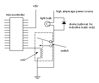
When you place an iron shaft inside a coil of wire and pass current through the wire, the magnetic field moves the iron shaft. If that iron shaft is part of a switch, the switch can be turned on and off by putting current through the coil, which moves the shaft, closing the contact (see diagram below).
Note the diode in parallel with the load here. This is used only when the load is a motor, solenoid, or some other inductive load, and when it is switched off, will generate a blowback voltage. The diode protects against this. See my motes on motors for more detail. The current needed to move the shaft in the coil is very low (less than 10 milliamps) so the coil can be energized by an output pin of our microcontroller.
The current that can flow through the switch, however, is much higher. The lamp circuit is mostly separate from the microcontroller. A separate power source, with the amperage and voltage needed to turn on the lamp, is used. The power source, the lamp, and the switch side of the relay are all placed in series, and the opposite side of the switch is grounded. When the coil is energized, the switch is physically moved by the magnetic force created, the lamp circuit is completed, and the lamp turns on.
Notice that the coil and the lamp circuit are connected to the same ground, however. This applies only if we are switching a DC circuit (more on AC later). Relays are also useful when you want to replace a switch in an existing electronic device. If you replace the switch with the coil of a relay, the microcontroller can control the device just as if the button were pressed. Because a relay is a mechanical switch, it can be somewhat slow (a few milliseconds to close). So relays aren`t very effective when you want to turn them on and off rapidly. Sometimes you need to switch a high current circuit rapidly. In this case you would use a switching transistor. A transistor is a device that can work as a switch or an amplifier. It allows control of a large current by a smaller current as does a relay. Unlike a relay, however, a transistor is not mechanical, and can operate much faster than a relay. For the moment, we`ll discuss using transistors as switches. There are several types of transistors and they come in two major classes: bipolar transistors, and field-effect transistors, or FETs.
For the moment, we`ll be talking only about bipolar transistors. All, however have some similar properties. They all have three connections, referred to as the base, the collector, and the emitter (on FET transistors, the three connections are the gate, the source and the drain). By putting a small voltage/current on the base of a transistor, you allow a larger current to flow from the collector to the emitter.
Among bipolar transistors, there are two types: NPN transistors, and PNP transistors. NPN transistors require a small positive voltage on the base relative to the voltage on the collector to turn on, whereas PNP transistors require a small negative voltage on the base. We`ll use NPN 🔗 External reference
Related Circuits
This page shows some methods of track routing control for Stall-Motor type switch machines. The principle method uses a 2 Pole - Multi Position rotary switch while an alternate uses optoisolators and transistors to select the routes. The last...
Crystal Y1 generates a fundamental frequency clock signal of 14.31818 MHz. U31 is a Dual Voltage Controlled Oscillator (VCO) that produces a 14.31818 MHz clock signal, referred to as the color clock, at pin 10. The output frequency can...
The circuits on this page are for motor controls using Push buttons and would typically be found in commercial and industrial installations. The circuits do not show the wiring of the motors themselves as this depends on the particular...
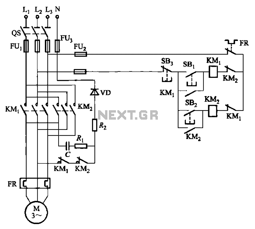
The circuit depicted in Figure 3-146 eliminates the need for a step-down transformer by utilizing the principle of energy storage through capacitor discharge for braking. It can be employed to frequently start and stop a motor with a power...
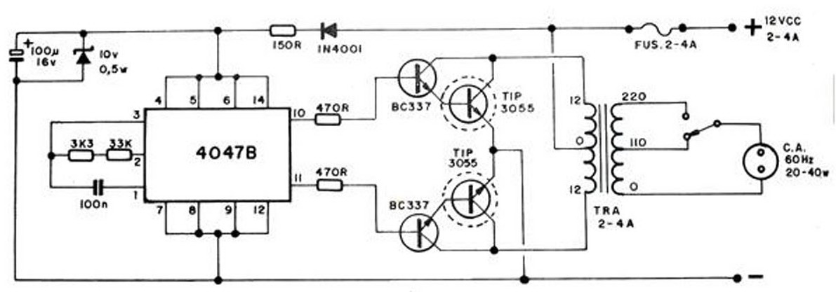
The converter transforms 12 VDC to 220 VAC, allowing for the conversion of 12 volts DC into 220 volts AC. The circuit diagram provided illustrates a simple converter circuit. This DC to AC converter can supply voltage for a...

The inverting input is maintained at a low level via a 10K resistor when the circuit is powered on but not in use. During measurement activities, including calibration measurements where the input is floating, this resistor is disconnected. The...
Warning: include(partials/cookie-banner.php): Failed to open stream: Permission denied in /var/www/html/nextgr/view-circuit.php on line 713
Warning: include(): Failed opening 'partials/cookie-banner.php' for inclusion (include_path='.:/usr/share/php') in /var/www/html/nextgr/view-circuit.php on line 713