
Controlling Stepper Motor with a Parallel Port

The stepper motor driver circuit described is designed to interface a unipolar stepper motor with a computer's parallel port, enabling precise control over the motor's movement. This circuit typically includes a microcontroller or a dedicated driver IC that interprets the signals from the parallel port and converts them into the necessary control signals for the stepper motor.
The unipolar stepper motor operates by energizing its coils in a specific sequence, allowing it to move in discrete steps. Each pulse sent from the parallel port corresponds to one step of the motor. The circuit may consist of several components, including transistors or MOSFETs to switch the motor coils on and off, resistors to limit current, and diodes for flyback protection to prevent voltage spikes when the coils are de-energized.
For a typical unipolar stepper motor requiring 48 steps per revolution, the driver circuit must generate a sequence of 48 pulses to complete one full rotation. The software on the computer side will need to be programmed to send these pulses in the correct order and timing to achieve smooth and controlled motion.
The driver circuit may also include a power supply section to provide the necessary voltage and current levels for the stepper motor's operation, as unipolar stepper motors often require higher voltages compared to the logic levels used by the parallel port.
Overall, the project presents an excellent opportunity for experimentation and learning, allowing users to explore robotics and automation applications through the controlled movement of stepper motors.This is an easy to build stepper motor driver that will allow you to precisely control a unipolar stepper motor through your computer`s parallel port. With a stepper motor you can build a lot of interesting gadgets such as robots, elevator, PCB drilling mill, camera panning system, automatic fish feeder, etc.
If you have never worked with stepper motors before you will surely have a lot of fun with this project. Stepper motors are very different from a regular DC motors. Instead of spinning like DC motors do, stepper motor steps at a specific resolution for each pulse. The motor that we are using needs 48 steps / pulses just to complete a single revolution! That 🔗 External reference
Related Circuits
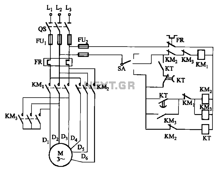
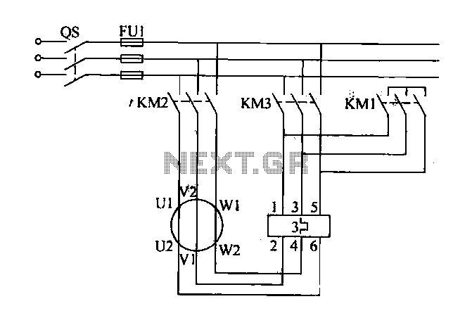
The circuit depicted in Figure 3-98 demonstrates how motor starting and low-speed operation are managed using switch SA. By adjusting the time relay KT, the motor's operation can transition from low speed to high-speed operation within a specified time...
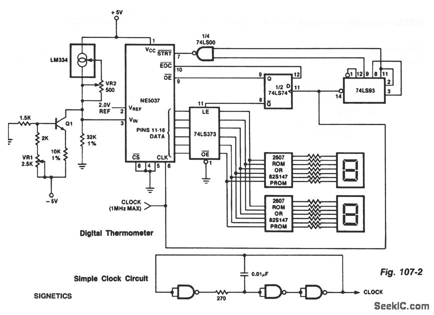
The ROMs or PROMs must contain the correct code for converting data from the NE5037, which serves as the address for the ROMs or PROMs, into the appropriate segment driver codes. The displayed temperature can be converted to degrees...
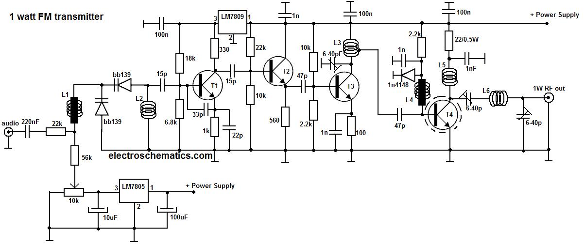
This portable FM transmitter features a limiter, a microphone amplifier, and PLL digital tuning, all integrated onto a single circuit board. The RF power output can be switched between 1 W (high) and 0.2 W (low). The schematic is...
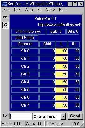
PulsePar turns a PC into a multi-channel pulse generator utilizing the parallel port. The period, duty and phase of each channel are adjustable so as to be used in PWM systems as well as in testing servo and stepper...
Traditional control methods for fan power equipment involve manual or relay control, which often leads to issues of poor reliability and flexibility. For instance, when the motor capacity is large, the startup process can be prolonged, resulting in high...
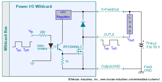
The embedded I/O board offers isolated high voltage switch inputs and eight high current, high voltage DC outputs. It utilizes optically isolated, open drain N-MOSFET transistors functioning as solid state relays (SSR) to control various resistive or inductive loads....
Warning: include(partials/cookie-banner.php): Failed to open stream: Permission denied in /var/www/html/nextgr/view-circuit.php on line 713
Warning: include(): Failed opening 'partials/cookie-banner.php' for inclusion (include_path='.:/usr/share/php') in /var/www/html/nextgr/view-circuit.php on line 713