
Controlling The Real World With Computers
The described hardware is a PC-based ISA (Industry Standard Architecture) data acquisition and control board designed for various applications that require analog input and output capabilities. The board is constructed with a tinned and masked surface, which enhances its durability and reliability in electronic environments.
The core functionality of the board revolves around its ability to handle up to eight analog inputs, facilitated by an 8-channel, 8-bit analog-to-digital converter (ADC). This ADC enables the board to convert analog signals into digital data, which can be processed by a PC. Notably, one of the channels is equipped with a microphone preamplifier, allowing for the direct connection of microphones and the amplification of audio signals before conversion.
In addition to its input capabilities, the board also features two 8-bit digital-to-analog converters (DACs). These DACs are responsible for generating analog output signals from digital data, making the board suitable for applications that require control signals or audio output.
The design of the board allows for seamless integration into a PC system via the ISA bus, which provides the necessary communication interface between the board and the computer. The use of an ISA architecture ensures compatibility with a wide range of PC hardware and software environments, making it a versatile choice for developers and engineers engaged in data acquisition and control projects.
Overall, this ISA data acquisition and control board serves as a fundamental component for interfacing with various sensors and actuators, enabling the collection and processing of analog signals in real-time applications.The hardware is shown in the picture (might take a little while to load). Don`t be the least bit concerned if you don`t understand everything in the first few paragraphs below. Their purpose is to provide a brief description of the hardware to those who understand the terminology.
The terms will be second-nature by the time you finish the tutorial. Just skim the information, make a note of the ordering information and Super Start, then move on to the circuit description below. The hardware is a tinned, masked PC-based ISA data acquisition and control board that * accepts up to 8 analog inputs through its 8 channel, 8-bit analog to digital converter (one has a mike preamp) * produces analog output through 2 8-bit dig 🔗 External reference
Related Circuits
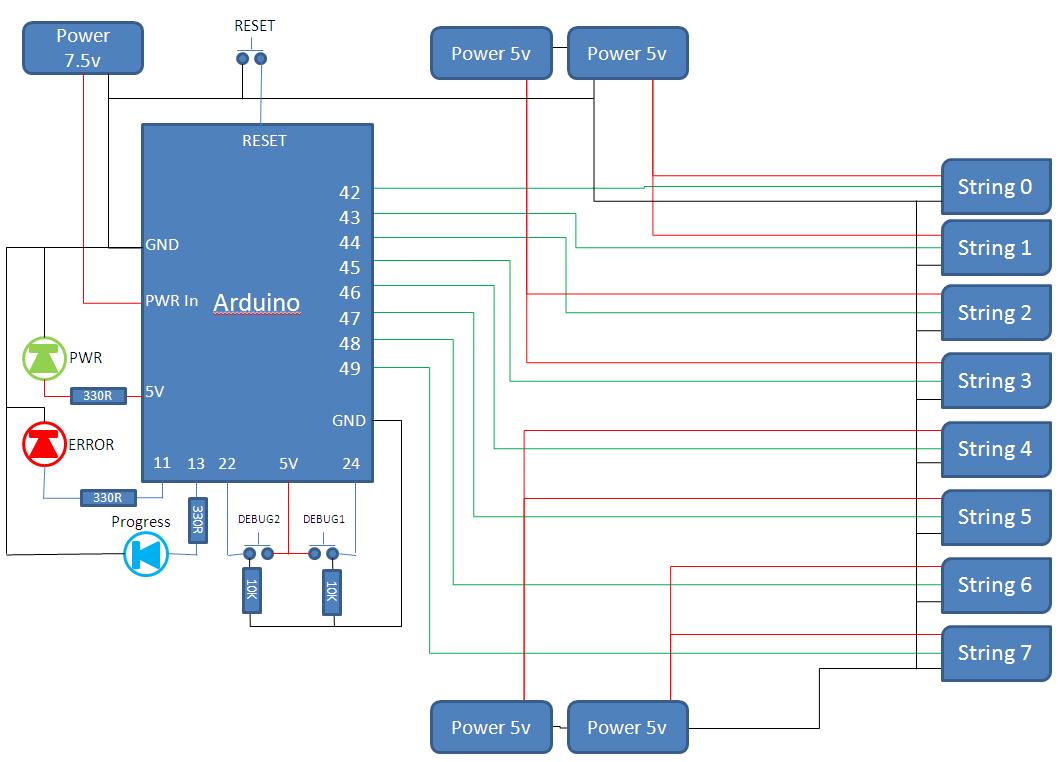
This project develops a Christmas lights controller for GE Color Effects lights, enabling programmed control of up to eight sets of lights. It includes a function-specific language for programming light patterns and an emulation environment for testing programs before...
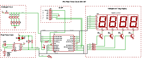
PIC RTC: A Real Time Clock IC using the DS1307 and a PIC microcontroller. This PIC project utilizes an I2C Real Time Clock chip and a display to create a four-digit standard desk clock. The described project incorporates a DS1307...
The development of a solar energy street lamp control device has progressed through three stages. The first generation featured a simple and crude function, allowing the light to be turned on or off, but required connection to a light-sensitive...
Control a small DC motor using an H-bridge with an Arduino Uno. The objective is to enable the motor to rotate in different directions based on left and right key presses on a keyboard. The provided code includes the...
The circuit monitors PC keyboard activity through a five-pin DIN connector J1. When a key is pressed, the keyboard transmits a series of negative-going pulses on pin 2. In conjunction with Q1 and C3, the operational amplifier operates as...
The F84 MRTC was my second design of a miniature real-time controller. This version uses PIC16F84 running with a low power X-tal 32,768Hz. The scheduler for 6-channel output was saved in EEPROM. No terminal for serial downloading of the...