
Simulating and controlling GE Color Effects Lights with Arduino
This Christmas lights controller project employs the Arduino Mega 2560 microcontroller to manage the GE Color Effects lighting system, which features RGB LEDs in each bulb, allowing for extensive customization of light displays. The firmware developed for the Arduino interprets a series of short integer commands that dictate specific lighting patterns. These commands are organized in a structured array, providing a straightforward method for defining complex light sequences.
The firmware can be compiled to run on a PC, facilitating the use of a lights emulator that visually simulates the light patterns defined in the firmware. This emulator is particularly useful for testing and refining lighting sequences before actual deployment, ensuring that users can visualize their designs without needing to set up the physical lights.
In addition to the firmware and emulator, a higher-level instruction set compiler is included in the project. This tool converts user-defined patterns into the necessary short integer array format required by the firmware, streamlining the programming process and enhancing user accessibility.
The design of the hardware has been optimized by utilizing a common ground configuration, which simplifies the wiring and reduces potential noise issues associated with isolated systems. This choice has proven effective in initial tests, allowing stable operation across multiple light strings.
The transition from the Arduino Pro to the Mega 2560 was necessitated by memory constraints encountered during development. The Mega 2560, with its increased RAM and flash memory, supports more complex patterns and allows for more extensive data storage, optimizing performance and functionality.
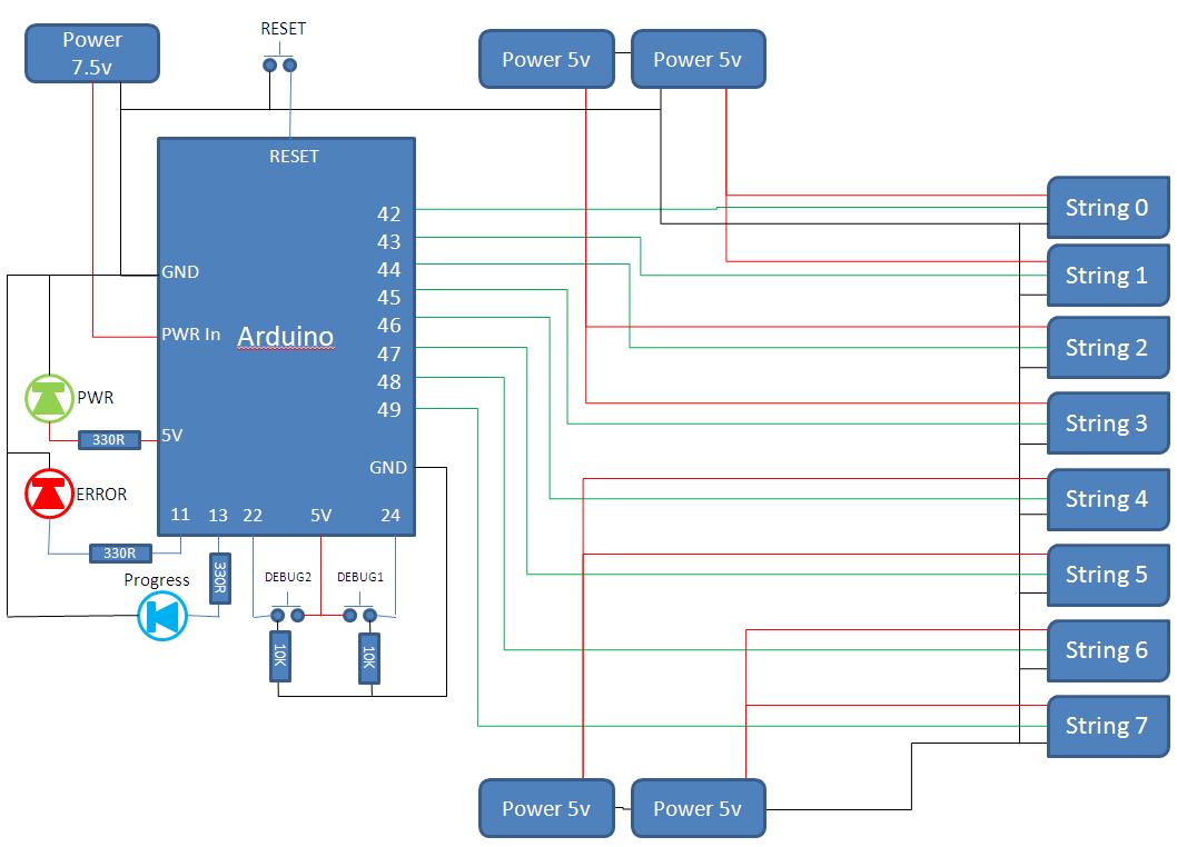
Powering the system involves using a 3A 5V adapter for every two strings of lights, requiring multiple adapters for larger setups. A reset button is integrated into the circuit, allowing for quick resets of the program without disrupting power to the bulbs, although a full power cycle may still be needed to address certain addressing issues.
Each string of GE Color Effects lights consists of 50 individually addressable bulbs, enabling granular control over color and brightness. The initialization process assigns bulb addresses sequentially, ensuring consistent control from the controller to the last bulb in the string. Brightness control is also facilitated through a broadcast command to a designated bulb, further enhancing the system's versatility. Overall, this project represents a comprehensive approach to programmable Christmas lighting, merging hardware and software to create a dynamic and customizable lighting experience.This project builds a Christmas lights controller for the GE Color Effects lights allowing programmed control of up to 8 sets of Christmas lights. Furthermore, it provides a function specific language for programming patterns for these lights and an emulation environment for testing the programs requiring the lights to be built or hung.
Arduino - If you have never heard of an Arduino, then I suggest you check out their site. They design and sell an open-source microprocessor platform which is great for building programmable electronic gadgets for those with limited electronics experience. GE Color Effects - These have to be the coolest Christmas lights ever for the hacker. Each bulb contains a red, green and blue LED and can be controlled individually or as a group by sending instructions down a single data line.
For a description of what they are and how they work, checkout this article which also provides basic control information that Robert Quattlebaum (darco) reverse engineered. While you are at it, do some Youtube searching for some very cool demos of what can be done with a microprocessor and a set of these lights (The ten string Christmas tree has to be seen to be believed).
The first program is the firmware which runs on the Arduino Mega to control the lights. It does this by reading a set of instructions which are expressed in the form of an array of short integers for each string of lights which tell the firmware what patterns to generate with the lights. The firmware can also be cross compiled and run on the PC where they can do the same job but control a lights emulator.
On the PC, I use the express version of VC+ to compile it. The second program is the lights emulator. This will emulate one or more sets of lights arranging them on screen according to your desired layout. When you run the firmware on the PC, this firmware will send the instructions to the emulator which will display the lights as they would appear.
I use the express version of VC# to compile it. The final program is a compiler (or more correctly an assembler) which takes a higher level instruction set and generates the required array of short integers the firmware uses to tell it what to do with the lights. I use the express version of VC# to compile it. I have significantly simplified the hardware design by removing the isolation circutry and going with a common ground configuration across multiple adapters.
I was concerned about this causing problems but it seems to work ok. In my first prototype, I used an Arduino Pro. It is cheap and works well but I quickly ran into memory issues as it only has 2K of RAM. Even with several refactorings to minimise memory use, I found I was running out of memory controlling 1 to 2 sets of lights. So I upgraded to the Arduino Mega 2560 with 8K of RAM. Still paltry but enough if you are very frugal with your memory use and you put all the static data such as the instructions into the more generous 256K of flash memory.
The Color Effects light comes with a 3A 5V adapter which is powerful enough to run 2 strings of lights. With 8 strings this requires 4 adapters and a 7. 5V adapter to run the arduino. The circuit also includes some key elements which make it easy to use/test: A reset button which resets the program.
as it does not cut power to the lights it does not reset any bulb addressing issues so sometimes you still need to cut the power It is also worth making a few comments about the lights themselves. Each string of lights is 50 bulbs long. Bulb addresses are established during initialisation which using my firmware means they will be always numbered 0.
49 in order from the controller to the end (but they don`t have to be). Each bulb can be individually controlled in terms of color and brightness. Brightness can also be controlled using a broadcast command to the mythical bulb 63. The bulb control protocol involves sending a pattern of low an 🔗 External reference
Related Circuits
A custom Lo-fi Arduino Guitar Pedal has been developed, utilizing a repurposed enclosure and twisted pair converters. Currently, it features a single output, with potential for future expansion. The design includes a digital delay effect, which was initially intended...
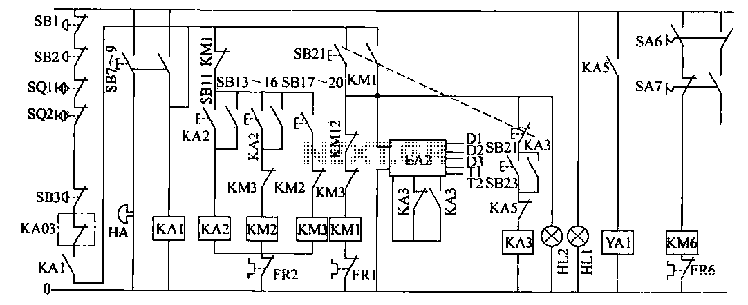
The operation control circuit is primarily managed by the button switch SB21. The contactor KM1, composed of the main contactor KM1, directly controls the operation of the main motor M1. The main motor M1 serves as the prime mover,...
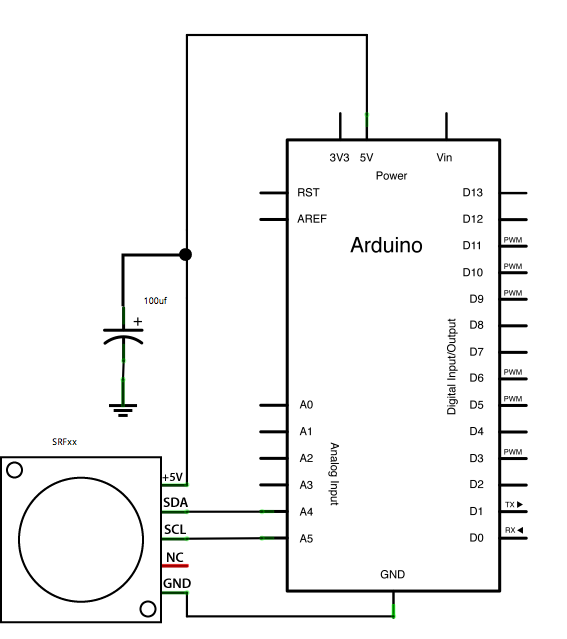
This example demonstrates how to read a Devantech SRFxx, an ultrasonic range finder that communicates via the I2C synchronous serial protocol, using Arduino's Wire Library. The I2C protocol utilizes two wires for data transmission: a serial clock pin (SCL)...
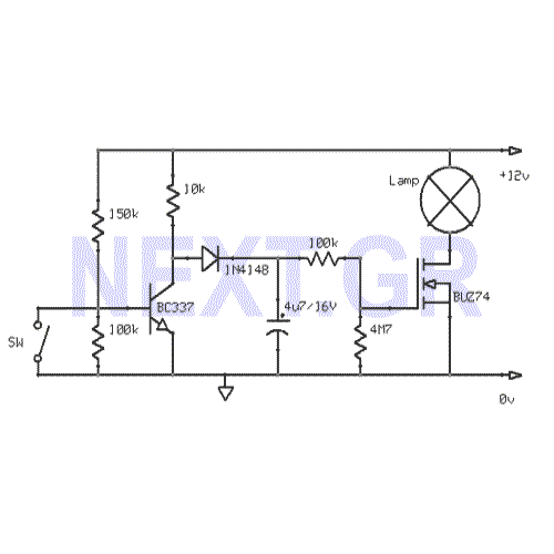
This circuit gradually switches the internal lights of a car on and off. The delay time can be adjusted by changing the values of the 10k and 4.7M resistors, as well as the capacitor. The circuit operates by utilizing a...
The bar graph, which consists of a series of LEDs arranged in a line similar to those found in audio displays, serves as a common hardware interface for analog sensors. It is constructed from a row of LEDs, an...

Most cars lack delayed interior lights. The presented circuit addresses this issue by gradually switching the interior lights on and off. This feature facilitates activities such as locating the ignition keyhole after the car door has been closed. The...